How to Use MSP432P4111 Breakout Board: Examples, Pinouts, and Specs
Introduction
The MSP432P4111 Breakout Board is a development platform built around the MSP432P4111 microcontroller. This microcontroller is known for its low power consumption, high performance, and advanced features, making it ideal for a wide range of embedded systems applications. The breakout board provides easy access to the microcontroller's pins and peripherals, simplifying prototyping and testing.
Explore Projects Built with MSP432P4111 Breakout Board


Explore Projects Built with MSP432P4111 Breakout Board
Common Applications and Use Cases
- Low-power IoT devices
- Sensor interfacing and data acquisition
- Real-time control systems
- Wearable technology
- Educational and research projects in embedded systems
Technical Specifications
Key Technical Details
- Microcontroller: MSP432P4111 (ARM Cortex-M4F core)
- Operating Voltage: 1.62V to 3.7V
- Clock Speed: Up to 48 MHz
- Flash Memory: 256 KB
- SRAM: 64 KB
- GPIO Pins: 84 (configurable as digital I/O, PWM, or peripheral functions)
- Communication Interfaces:
- 4x UART
- 4x SPI
- 4x I2C
- ADC: 14-bit, up to 24 channels
- Timers: 8x 16-bit timers
- Power Modes: Active, Low-Power, and Deep Sleep modes
- Debugging: Onboard JTAG/SWD interface
- Dimensions: 2.5 x 2.0 inches
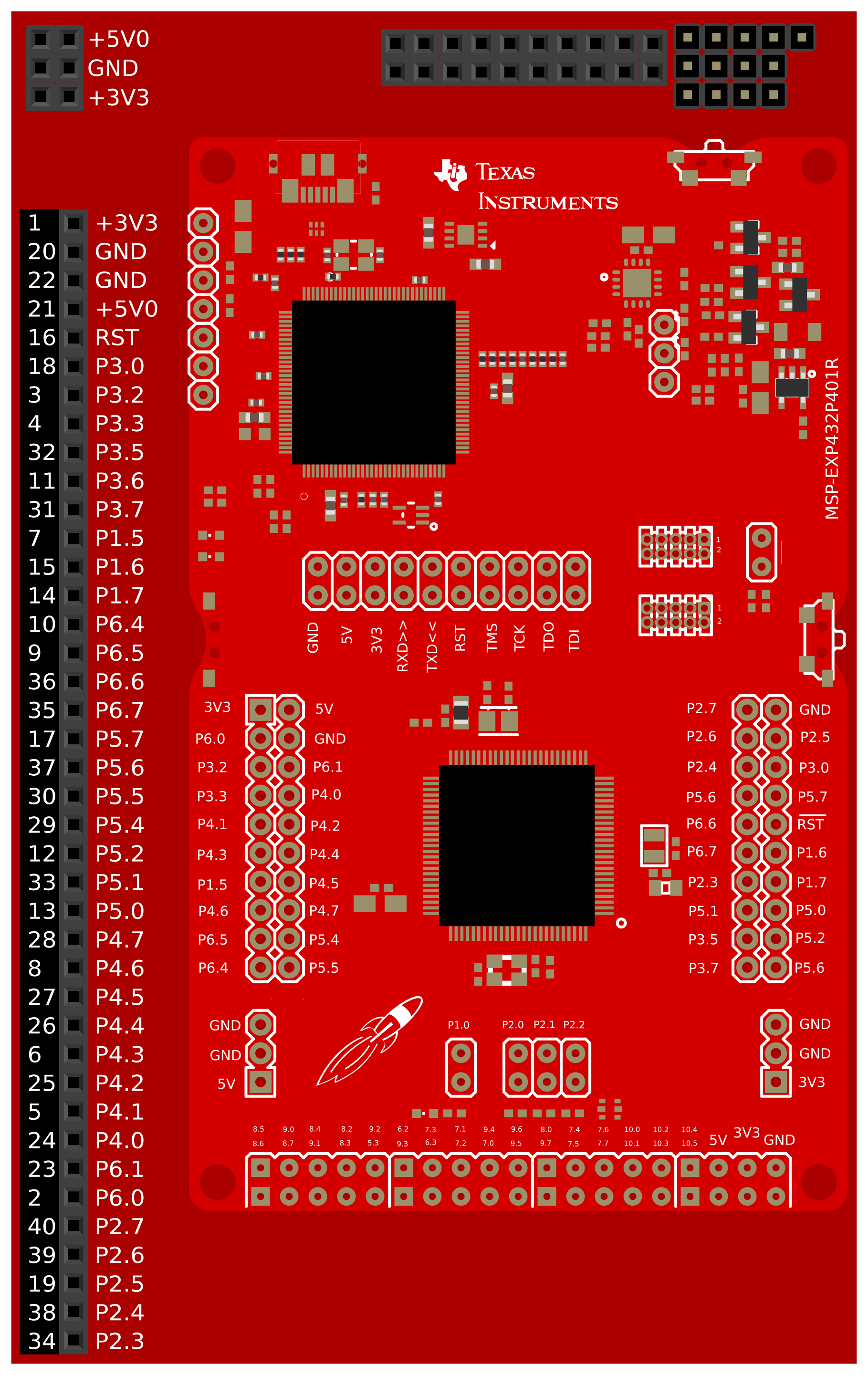
Pin Configuration and Descriptions
The MSP432P4111 Breakout Board provides access to all the microcontroller's pins via headers. Below is a summary of the key pin functions:
| Pin Name | Function | Description |
|---|---|---|
| VCC | Power Input | Connect to a 1.62V–3.7V power source. |
| GND | Ground | Common ground for the circuit. |
| P1.0 - P1.7 | GPIO, ADC, PWM | General-purpose I/O pins, configurable for analog or digital functions. |
| P2.0 - P2.7 | GPIO, ADC, PWM | Additional GPIO pins with analog and PWM capabilities. |
| P3.0 - P3.7 | UART, SPI, I2C, GPIO | Communication pins, configurable for UART, SPI, I2C, or general-purpose I/O. |
| P4.0 - P4.7 | GPIO, ADC, PWM | General-purpose I/O pins with analog and PWM support. |
| RESET | Reset Input | Active-low reset pin to restart the microcontroller. |
| SWDIO | Debug Interface (Data) | Serial Wire Debug data pin for programming and debugging. |
| SWCLK | Debug Interface (Clock) | Serial Wire Debug clock pin for programming and debugging. |
| XTAL_IN | External Oscillator Input | Input for an external crystal oscillator. |
| XTAL_OUT | External Oscillator Output | Output for an external crystal oscillator. |
Usage Instructions
How to Use the MSP432P4111 Breakout Board in a Circuit
Powering the Board:
- Connect the VCC pin to a regulated power supply (1.62V–3.7V).
- Ensure the GND pin is connected to the common ground of your circuit.
Programming the Microcontroller:
- Use the onboard JTAG/SWD interface to program the MSP432P4111.
- Compatible IDEs include Code Composer Studio (CCS) and Keil µVision.
Connecting Peripherals:
- Use the GPIO pins to interface with sensors, actuators, or other devices.
- Configure the pins in software for the desired function (e.g., digital I/O, ADC, PWM).
Using Communication Interfaces:
- Connect UART, SPI, or I2C devices to the corresponding pins (e.g., P3.0–P3.7).
- Configure the communication protocol in software.
Debugging:
- Connect a debugger to the SWDIO and SWCLK pins for real-time debugging and monitoring.
Important Considerations and Best Practices
- Voltage Levels: Ensure all connected devices operate within the MSP432P4111's voltage range (1.62V–3.7V).
- Pin Configuration: Configure each pin in software before use to avoid conflicts or damage.
- Power Consumption: Utilize the microcontroller's low-power modes to optimize energy efficiency in battery-powered applications.
- External Oscillator: For precise timing, connect an external crystal oscillator to the XTAL_IN and XTAL_OUT pins.
Example: Interfacing with an Arduino UNO
The MSP432P4111 Breakout Board can communicate with an Arduino UNO via UART. Below is an example of how to send data from the MSP432P4111 to the Arduino UNO:
MSP432P4111 Code (Using Code Composer Studio)
#include "msp.h"

void UART_Init(void) {
    // Configure UART on P3.2 (TX) and P3.3 (RX)
    P3->SEL0 |= BIT2 | BIT3;  // Set P3.2 and P3.3 to UART mode
    P3->SEL1 &= ~(BIT2 | BIT3);

    EUSCI_A2->CTLW0 = EUSCI_A_CTLW0_SWRST;  // Put UART in reset state
    EUSCI_A2->CTLW0 = EUSCI_A_CTLW0_SSEL__SMCLK;  // Use SMCLK as clock source
    EUSCI_A2->BRW = 26;  // Set baud rate to 9600 (assuming 3 MHz clock)
    EUSCI_A2->MCTLW = (0 << EUSCI_A_MCTLW_OS16_OFS);  // Disable oversampling
    EUSCI_A2->CTLW0 &= ~EUSCI_A_CTLW0_SWRST;  // Release UART from reset
}

void UART_SendChar(char c) {
    while (!(EUSCI_A2->IFG & EUSCI_A_IFG_TXIFG));  // Wait for TX buffer to be ready
    EUSCI_A2->TXBUF = c;  // Send character
}

void main(void) {
    WDT_A->CTL = WDT_A_CTL_PW | WDT_A_CTL_HOLD;  // Stop watchdog timer
    UART_Init();  // Initialize UART

    while (1) {
        UART_SendChar('H');  // Send 'H' to Arduino
        UART_SendChar('i');  // Send 'i' to Arduino
        UART_SendChar('\n');  // Send newline character
        for (volatile int i = 0; i < 100000; i++);  // Delay
    }
}
Arduino UNO Code
void setup() {
    Serial.begin(9600);  // Initialize serial communication at 9600 baud
}

void loop() {
    if (Serial.available() > 0) {
        char received = Serial.read();  // Read data from MSP432P4111
        Serial.print("Received: ");
        Serial.println(received);  // Print received data to the Serial Monitor
    }
}
Troubleshooting and FAQs
Common Issues and Solutions
Microcontroller Not Responding:
- Ensure the board is powered correctly (1.62V–3.7V).
- Check the RESET pin to ensure it is not held low.
Communication Issues:
- Verify the baud rate and communication settings match between devices.
- Check the wiring of UART, SPI, or I2C connections.
Debugging Not Working:
- Ensure the SWDIO and SWCLK pins are connected to the debugger.
- Verify the debugger is configured for the MSP432P4111.
Incorrect Pin Behavior:
- Double-check the pin configuration in your code.
- Ensure no conflicting peripherals are assigned to the same pin.
FAQs
Can I power the board with a 5V supply? No, the MSP432P4111 operates at a maximum voltage of 3.7V. Use a voltage regulator if needed.
What IDEs are supported? The MSP432P4111 is compatible with Code Composer Studio (CCS), Keil µVision, and IAR Embedded Workbench.
How do I reduce power consumption? Use the microcontroller's low-power modes and disable unused peripherals in software.