Cirkit Designer
Your all-in-one circuit design IDE
Home /
Component Documentation
How to Use motor power window: Examples, Pinouts, and Specs
Introduction
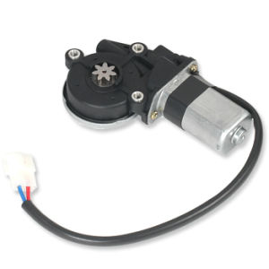
The Motor Power Window is an essential component in modern automotive systems, designed to control the up and down movement of a car's power window. This motor is typically integrated into the door assembly and is responsible for the smooth and efficient operation of the window mechanism. It is widely used in various types of vehicles, including sedans, SUVs, and trucks.
Explore Projects Built with motor power window
Arduino UNO Controlled Motor with Limit Switches and Pushbutton Interface
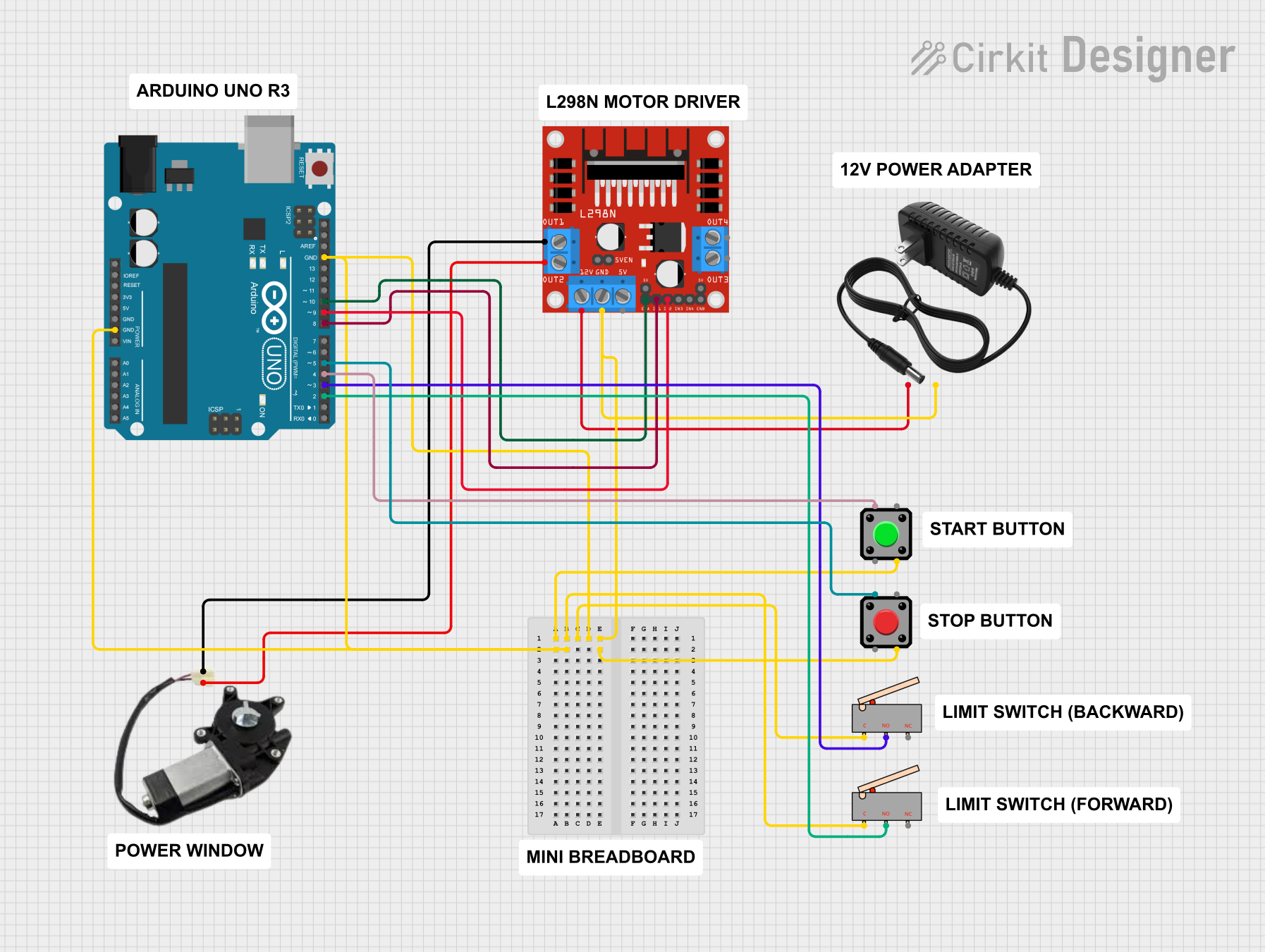
This circuit controls a power window using an Arduino UNO and an L298N DC motor driver. It features two limit switches to define the window's end positions and two pushbuttons for start and stop control. The Arduino's embedded code manages the motor's direction and speed, responding to limit switch activation and button presses to start, stop, and reverse the motor.
PLC-Controlled Power Window System with Infrared Sensing and Relay Module

This circuit is designed to control a motorized window system using a PLC (Programmable Logic Controller) and an array of sensors and switches. It includes power supplies for 12V and 24V DC, an MCB (Miniature Circuit Breaker) for protection, and a relay module interfaced with an Arduino for additional control logic. The PLC manages inputs from pushbuttons, a 3-position switch, infrared proximity sensors, and an emergency stop, and it controls outputs such as the motor speed controller, lamps, and solenoid valves.
Arduino UNO and Cytron Motor Driver Controlled Two-Wheel Mobile Robot
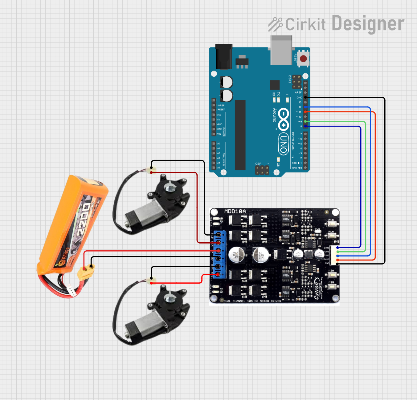
This circuit is a control system for a two-wheel mobile robot, utilizing an Arduino UNO to manage a Cytron motor driver. The Arduino controls the direction and speed of two power window motors via PWM and direction signals, powered by a LiPo battery.
Battery-Powered DC Motor Control with Rocker Switch
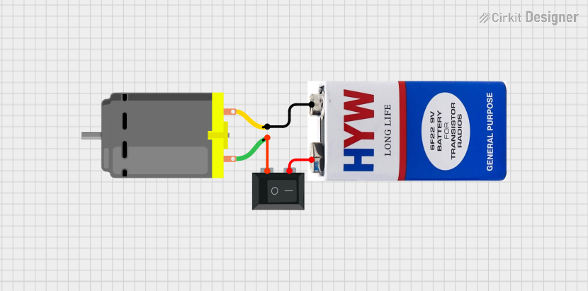
This circuit controls a DC motor using a 9V battery and a single-pole single-throw (SPST) rocker switch. The switch allows the user to turn the motor on and off by connecting or disconnecting the power from the battery to the motor.
Explore Projects Built with motor power window
Arduino UNO Controlled Motor with Limit Switches and Pushbutton Interface
This circuit controls a power window using an Arduino UNO and an L298N DC motor driver. It features two limit switches to define the window's end positions and two pushbuttons for start and stop control. The Arduino's embedded code manages the motor's direction and speed, responding to limit switch activation and button presses to start, stop, and reverse the motor.
PLC-Controlled Power Window System with Infrared Sensing and Relay Module
This circuit is designed to control a motorized window system using a PLC (Programmable Logic Controller) and an array of sensors and switches. It includes power supplies for 12V and 24V DC, an MCB (Miniature Circuit Breaker) for protection, and a relay module interfaced with an Arduino for additional control logic. The PLC manages inputs from pushbuttons, a 3-position switch, infrared proximity sensors, and an emergency stop, and it controls outputs such as the motor speed controller, lamps, and solenoid valves.
Arduino UNO and Cytron Motor Driver Controlled Two-Wheel Mobile Robot
This circuit is a control system for a two-wheel mobile robot, utilizing an Arduino UNO to manage a Cytron motor driver. The Arduino controls the direction and speed of two power window motors via PWM and direction signals, powered by a LiPo battery.
Battery-Powered DC Motor Control with Rocker Switch
This circuit controls a DC motor using a 9V battery and a single-pole single-throw (SPST) rocker switch. The switch allows the user to turn the motor on and off by connecting or disconnecting the power from the battery to the motor.
Common Applications and Use Cases
- Automotive Industry: Used in car doors to automate the window movement.
- Robotics: Can be repurposed for robotic arms or other moving parts.
- Home Automation: Suitable for custom projects requiring linear motion.
Technical Specifications
Key Technical Details
| Parameter | Value |
|---|---|
| Operating Voltage | 12V DC |
| Current Rating | 2A - 5A (depending on load) |
| Power Rating | 24W - 60W |
| Speed | 50 - 100 RPM |
| Torque | 10 - 20 Nm |
| Operating Temperature | -20°C to 70°C |
| Weight | 500g - 1kg |
Pin Configuration and Descriptions
| Pin Number | Pin Name | Description |
|---|---|---|
| 1 | VCC | Power supply (12V DC) |
| 2 | GND | Ground |
| 3 | IN1 | Control signal for direction (Input) |
| 4 | IN2 | Control signal for direction (Input) |
Usage Instructions
How to Use the Component in a Circuit
- Power Supply: Connect the VCC pin to a 12V DC power source and the GND pin to the ground.
- Control Signals: Use a microcontroller (e.g., Arduino UNO) to send control signals to IN1 and IN2 pins to control the direction of the motor.
Important Considerations and Best Practices
- Current Limiting: Ensure that the power supply can handle the current requirements of the motor to avoid overheating.
- Heat Dissipation: Provide adequate ventilation or heat sinks to manage heat generated during operation.
- Reverse Polarity Protection: Use diodes to protect the motor from damage due to reverse polarity.
Sample Arduino Code
// Define the control pins
const int IN1 = 8;
const int IN2 = 9;

void setup() {
  // Set the control pins as outputs
  pinMode(IN1, OUTPUT);
  pinMode(IN2, OUTPUT);
}

void loop() {
  // Move window up
  digitalWrite(IN1, HIGH); // Set IN1 high
  digitalWrite(IN2, LOW);  // Set IN2 low
  delay(5000);             // Run motor for 5 seconds

  // Stop motor
  digitalWrite(IN1, LOW);  // Set IN1 low
  digitalWrite(IN2, LOW);  // Set IN2 low
  delay(2000);             // Wait for 2 seconds

  // Move window down
  digitalWrite(IN1, LOW);  // Set IN1 low
  digitalWrite(IN2, HIGH); // Set IN2 high
  delay(5000);             // Run motor for 5 seconds

  // Stop motor
  digitalWrite(IN1, LOW);  // Set IN1 low
  digitalWrite(IN2, LOW);  // Set IN2 low
  delay(2000);             // Wait for 2 seconds
}
Troubleshooting and FAQs
Common Issues Users Might Face
Motor Not Running:
- Solution: Check the power supply and ensure it is providing the correct voltage and current.
- Tip: Verify the connections and ensure the control signals are correctly sent from the microcontroller.
Motor Overheating:
- Solution: Ensure proper ventilation and consider using a heat sink.
- Tip: Check for any obstructions in the window mechanism that might be causing excessive load.
Erratic Movement:
- Solution: Check the control signals and ensure they are stable and correctly timed.
- Tip: Use capacitors to filter out any noise in the control signals.
FAQs
Can I use a different voltage?
- The motor is designed for 12V DC. Using a different voltage may damage the motor or reduce its efficiency.
How do I reverse the motor direction?
- Swap the control signals on IN1 and IN2 pins to reverse the motor direction.
What should I do if the motor is noisy?
- Ensure the motor is properly mounted and check for any mechanical obstructions. Lubricate the moving parts if necessary.
By following this documentation, users can effectively integrate and troubleshoot the Motor Power Window in their projects, ensuring smooth and reliable operation.