Cirkit Designer Logo
Cirkit Designer
Your all-in-one circuit design IDE
Home / 
Component Documentation

How to Use CP2102: Examples, Pinouts, and Specs

Image of CP2102
Cirkit Designer LogoDesign with CP2102 in Cirkit Designer

Introduction

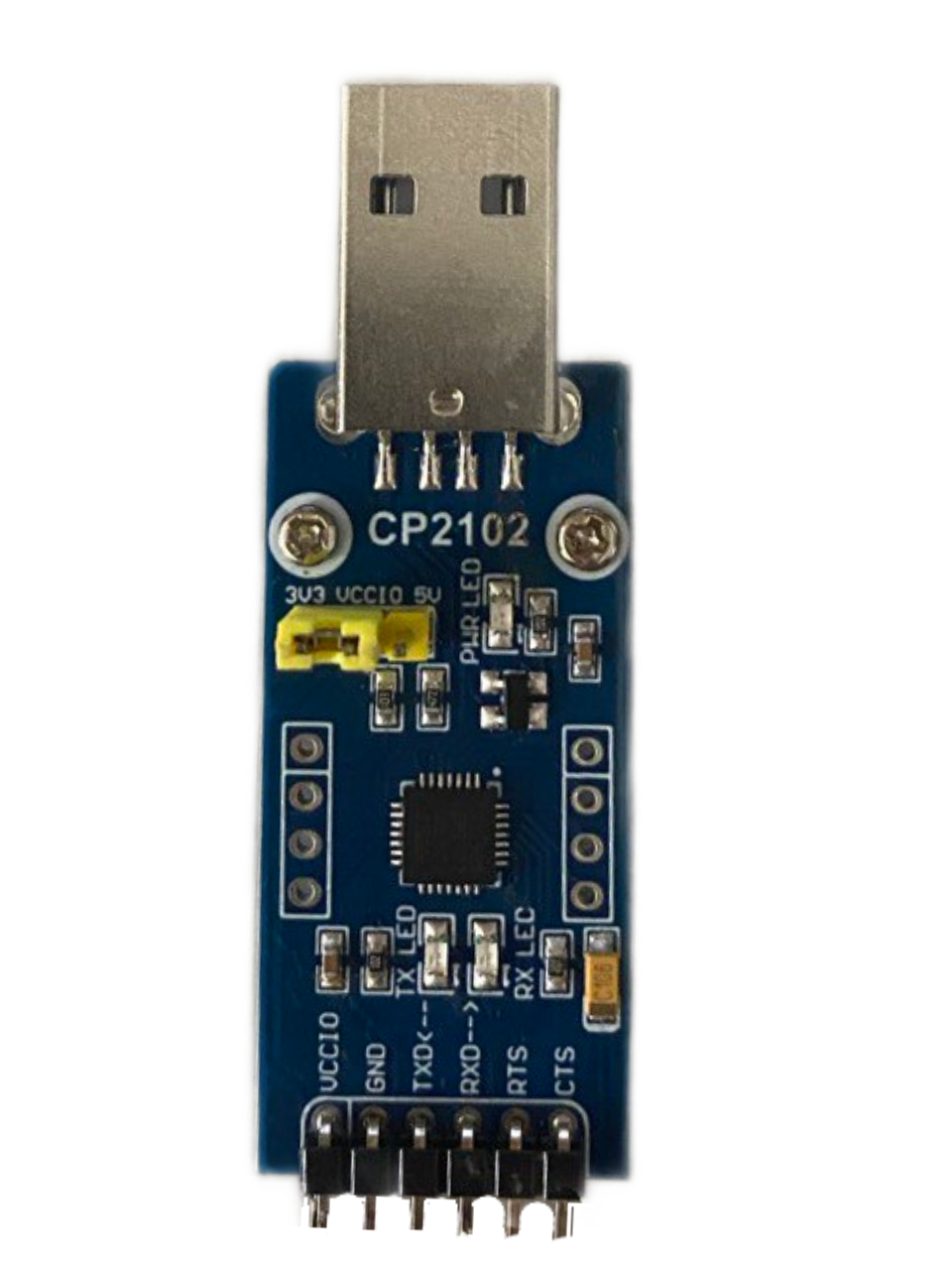
The CP2102, manufactured by Waveshare, is a USB to UART bridge controller designed to simplify the connection of serial devices to USB ports. It integrates a USB transceiver, oscillator, and EEPROM, eliminating the need for external components. With support for data rates up to 1 Mbps, the CP2102 is widely used in applications requiring reliable and high-speed serial communication.

Explore Projects Built with CP2102

Use Cirkit Designer to design, explore, and prototype these projects online. Some projects support real-time simulation. Click "Open Project" to start designing instantly!
Battery-Powered Raspberry Pi Pico GPS Tracker with Sensor Integration
Image of Copy of CanSet v1: A project utilizing CP2102 in a practical application
This circuit is a data acquisition and communication system powered by a LiPoly battery and managed by a Raspberry Pi Pico. It includes sensors (BMP280, MPU9250) for environmental data, a GPS module for location tracking, an SD card for data storage, and a WLR089-CanSAT for wireless communication. The TP4056 module handles battery charging, and a toggle switch controls power distribution.
Cirkit Designer LogoOpen Project in Cirkit Designer
Arduino Mega 2560 Based Security System with Fingerprint Authentication and SMS Alerts
Image of Door security system: A project utilizing CP2102 in a practical application
This circuit features an Arduino Mega 2560 microcontroller interfaced with a SIM800L GSM module, two fingerprint scanners, an I2C LCD display, an IR sensor, and a piezo buzzer. Power management is handled by a PowerBoost 1000 Basic Pad USB, a TP4056 charging module, and a Li-ion 18650 battery, with an option to use a Mini AC-DC 110V-230V to 5V 700mA module for direct power supply. The primary functionality appears to be a security system with GSM communication capabilities, biometric access control, and visual/audible feedback.
Cirkit Designer LogoOpen Project in Cirkit Designer
ESP32-Based Battery-Powered Multi-Sensor System
Image of Dive sense: A project utilizing CP2102 in a practical application
This circuit consists of a TP4056 module connected to a 3.7V LiPo battery, providing a charging interface for the battery. The TP4056 manages the charging process by connecting its B+ and B- pins to the battery's positive and ground terminals, respectively.
Cirkit Designer LogoOpen Project in Cirkit Designer
Battery-Powered Emergency Alert System with NUCLEO-F072RB, SIM800L, and GPS NEO 6M
Image of women safety: A project utilizing CP2102 in a practical application
This circuit is an emergency alert system that uses a NUCLEO-F072RB microcontroller to send SMS alerts and make calls via a SIM800L GSM module, while obtaining location data from a GPS NEO 6M module. The system is powered by a Li-ion battery and includes a TP4056 module for battery charging and protection, with a rocker switch to control power to the microcontroller.
Cirkit Designer LogoOpen Project in Cirkit Designer

Explore Projects Built with CP2102

Use Cirkit Designer to design, explore, and prototype these projects online. Some projects support real-time simulation. Click "Open Project" to start designing instantly!
Image of Copy of CanSet v1: A project utilizing CP2102 in a practical application
Battery-Powered Raspberry Pi Pico GPS Tracker with Sensor Integration
This circuit is a data acquisition and communication system powered by a LiPoly battery and managed by a Raspberry Pi Pico. It includes sensors (BMP280, MPU9250) for environmental data, a GPS module for location tracking, an SD card for data storage, and a WLR089-CanSAT for wireless communication. The TP4056 module handles battery charging, and a toggle switch controls power distribution.
Cirkit Designer LogoOpen Project in Cirkit Designer
Image of Door security system: A project utilizing CP2102 in a practical application
Arduino Mega 2560 Based Security System with Fingerprint Authentication and SMS Alerts
This circuit features an Arduino Mega 2560 microcontroller interfaced with a SIM800L GSM module, two fingerprint scanners, an I2C LCD display, an IR sensor, and a piezo buzzer. Power management is handled by a PowerBoost 1000 Basic Pad USB, a TP4056 charging module, and a Li-ion 18650 battery, with an option to use a Mini AC-DC 110V-230V to 5V 700mA module for direct power supply. The primary functionality appears to be a security system with GSM communication capabilities, biometric access control, and visual/audible feedback.
Cirkit Designer LogoOpen Project in Cirkit Designer
Image of Dive sense: A project utilizing CP2102 in a practical application
ESP32-Based Battery-Powered Multi-Sensor System
This circuit consists of a TP4056 module connected to a 3.7V LiPo battery, providing a charging interface for the battery. The TP4056 manages the charging process by connecting its B+ and B- pins to the battery's positive and ground terminals, respectively.
Cirkit Designer LogoOpen Project in Cirkit Designer
Image of women safety: A project utilizing CP2102 in a practical application
Battery-Powered Emergency Alert System with NUCLEO-F072RB, SIM800L, and GPS NEO 6M
This circuit is an emergency alert system that uses a NUCLEO-F072RB microcontroller to send SMS alerts and make calls via a SIM800L GSM module, while obtaining location data from a GPS NEO 6M module. The system is powered by a Li-ion battery and includes a TP4056 module for battery charging and protection, with a rocker switch to control power to the microcontroller.
Cirkit Designer LogoOpen Project in Cirkit Designer

Common Applications and Use Cases

  • USB-to-serial adapters for debugging and programming microcontrollers
  • Connecting legacy serial devices to modern computers
  • Embedded systems requiring USB communication
  • Serial communication in IoT devices
  • Prototyping and development of UART-based systems

Technical Specifications

The CP2102 is a versatile and compact device with the following key specifications:

Parameter Value
USB Protocol USB 2.0 Full-Speed
UART Data Rates Up to 1 Mbps
Operating Voltage 3.0 V to 3.6 V
GPIO Pins 4 configurable pins
EEPROM Integrated
Driver Support Windows, macOS, Linux
Package QFN-28

Pin Configuration and Descriptions

The CP2102 comes in a 28-pin QFN package. Below is the pin configuration:

Pin Number Pin Name Description
1 VDD Power supply input (3.0 V to 3.6 V)
2 GND Ground
3 TXD UART Transmit Data
4 RXD UART Receive Data
5 DTR Data Terminal Ready
6 RTS Request to Send
7 DSR Data Set Ready
8 CTS Clear to Send
9 RSTb Reset (active low)
10-13 GPIO.0-3 General-purpose I/O pins
14 USB+ USB D+ signal
15 USB- USB D- signal
16 NC No connection

Usage Instructions

How to Use the CP2102 in a Circuit

  1. Power Supply: Connect the VDD pin to a 3.3 V power source and GND to ground.
  2. USB Connection: Connect the USB+ and USB- pins to a USB port using a USB cable.
  3. UART Interface: Connect the TXD and RXD pins to the corresponding RX and TX pins of the UART device.
  4. Optional Pins: Use the GPIO pins for additional control or status signals as needed.
  5. Driver Installation: Install the appropriate CP2102 drivers for your operating system. These can be downloaded from the Waveshare website or the Silicon Labs website.

Important Considerations and Best Practices

  • Voltage Levels: Ensure that the UART device operates at 3.3 V logic levels to avoid damage.
  • Decoupling Capacitors: Place a 0.1 µF decoupling capacitor close to the VDD pin for stable operation.
  • Driver Installation: Verify that the correct drivers are installed before connecting the CP2102 to a computer.
  • Pin Protection: Avoid leaving unused pins floating; connect them to ground or configure them as needed.

Example: Connecting CP2102 to Arduino UNO

The CP2102 can be used to program or communicate with an Arduino UNO. Below is an example of how to use it with Arduino IDE:

Circuit Connections

  • Connect the CP2102 TXD pin to the Arduino RX pin.
  • Connect the CP2102 RXD pin to the Arduino TX pin.
  • Connect the CP2102 GND pin to the Arduino GND pin.
  • Connect the CP2102 VDD pin to a 3.3 V power source.

Arduino Code Example

// Example code to send data from Arduino to a PC via CP2102
void setup() {
  Serial.begin(9600); // Initialize serial communication at 9600 baud
}

void loop() {
  Serial.println("Hello from Arduino!"); // Send a message to the PC
  delay(1000); // Wait for 1 second
}

Troubleshooting and FAQs

Common Issues and Solutions

  1. Device Not Recognized by Computer

    • Ensure the CP2102 drivers are installed correctly.
    • Check the USB cable for damage or loose connections.
    • Verify that the USB+ and USB- pins are connected properly.
  2. No Data Transmission

    • Confirm that the TXD and RXD pins are connected to the correct UART pins.
    • Check the baud rate settings in the software and ensure they match the device.
  3. Overheating

    • Verify that the VDD pin is supplied with the correct voltage (3.3 V).
    • Ensure proper decoupling capacitors are in place.
  4. GPIO Pins Not Working

    • Check the configuration of the GPIO pins in the software.
    • Ensure the pins are not left floating or shorted.

FAQs

Q: Can the CP2102 operate at 5 V?
A: No, the CP2102 operates at 3.3 V. Using 5 V can damage the device.

Q: Where can I download the drivers?
A: Drivers can be downloaded from the Waveshare website or the Silicon Labs website.

Q: What is the maximum data rate supported by the CP2102?
A: The CP2102 supports data rates up to 1 Mbps.

Q: Can the CP2102 be used with macOS or Linux?
A: Yes, the CP2102 is compatible with Windows, macOS, and Linux operating systems.