Cirkit Designer
Your all-in-one circuit design IDE
Home /
Component Documentation
How to Use LED_GREEN: Examples, Pinouts, and Specs
Introduction
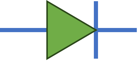
The LED_GREEN is a green Light Emitting Diode (LED) manufactured by Custom. It emits green light when an electric current passes through it. This component is widely used as an indicator in various electronic circuits due to its low power consumption, long lifespan, and high visibility.
Explore Projects Built with LED_GREEN
Arduino UNO LED Blinker with Resistor
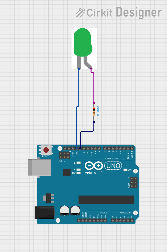
This circuit uses an Arduino UNO to control a green LED. The LED is connected to digital pin 13 through a 200-ohm resistor, and the Arduino code makes the LED blink on and off at one-second intervals.
Battery-Powered LED Array with Rocker Switch Control

This circuit consists of four green LEDs connected in parallel, powered by a 9V battery. A rocker switch is used to control the power to the LEDs, allowing them to be turned on or off simultaneously.
Solar-Powered Green LED Light
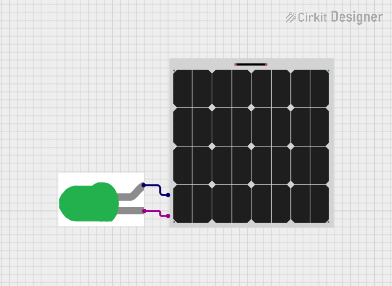
This circuit consists of a solar panel connected to a green LED. The solar panel provides power to the LED, causing it to light up when sufficient sunlight is available.
Wi-Fi Controlled LED Indicator using ESP8266 NodeMCU
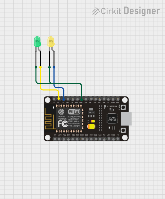
This circuit uses an ESP8266 NodeMCU microcontroller to control two LEDs, one green and one yellow. The green LED is connected to pin D1, and the yellow LED is connected to pin D2, with both LEDs sharing a common ground with the microcontroller.
Explore Projects Built with LED_GREEN
Arduino UNO LED Blinker with Resistor
This circuit uses an Arduino UNO to control a green LED. The LED is connected to digital pin 13 through a 200-ohm resistor, and the Arduino code makes the LED blink on and off at one-second intervals.
Battery-Powered LED Array with Rocker Switch Control
This circuit consists of four green LEDs connected in parallel, powered by a 9V battery. A rocker switch is used to control the power to the LEDs, allowing them to be turned on or off simultaneously.
Solar-Powered Green LED Light
This circuit consists of a solar panel connected to a green LED. The solar panel provides power to the LED, causing it to light up when sufficient sunlight is available.
Wi-Fi Controlled LED Indicator using ESP8266 NodeMCU
This circuit uses an ESP8266 NodeMCU microcontroller to control two LEDs, one green and one yellow. The green LED is connected to pin D1, and the yellow LED is connected to pin D2, with both LEDs sharing a common ground with the microcontroller.
Common Applications and Use Cases
- Status Indicators: Used in electronic devices to indicate power status, operational status, or error conditions.
- Display Panels: Incorporated in display panels for visual signaling.
- Decorative Lighting: Used in decorative lighting applications due to its vibrant green color.
- Prototyping: Commonly used in breadboard and prototyping projects for visual feedback.
Technical Specifications
Key Technical Details
| Parameter | Value |
|---|---|
| Forward Voltage | 2.0V - 2.2V |
| Forward Current | 20mA |
| Power Dissipation | 60mW |
| Peak Wavelength | 525nm |
| Viewing Angle | 30 degrees |
| Maximum Reverse Voltage | 5V |
| Operating Temperature Range | -40°C to +85°C |
Pin Configuration and Descriptions
| Pin Number | Pin Name | Description |
|---|---|---|
| 1 | Anode | Positive terminal (longer lead) |
| 2 | Cathode | Negative terminal (shorter lead) |
Usage Instructions
How to Use the Component in a Circuit
- Identify the Leads: The longer lead is the anode (positive), and the shorter lead is the cathode (negative).
- Connect to Power Source: Connect the anode to the positive terminal of the power source and the cathode to the negative terminal.
- Use a Current-Limiting Resistor: To prevent damage, use a current-limiting resistor in series with the LED. Calculate the resistor value using Ohm's Law: [ R = \frac{V_{supply} - V_{forward}}{I_{forward}} ] For example, with a 5V supply and a forward voltage of 2.1V: [ R = \frac{5V - 2.1V}{20mA} = 145\Omega ] Use the nearest standard resistor value, which is 150Ω.
Important Considerations and Best Practices
- Polarity: Ensure correct polarity when connecting the LED. Reversing the polarity can damage the LED.
- Current Limiting: Always use a current-limiting resistor to prevent excessive current flow.
- Heat Dissipation: Ensure adequate ventilation to prevent overheating, especially in high-power applications.
- Series and Parallel Configurations: When using multiple LEDs, consider the configuration (series or parallel) and adjust the resistor values accordingly.
Example Circuit with Arduino UNO
// Example code to blink a green LED connected to pin 13 of Arduino UNO

const int ledPin = 13; // Pin number where the LED is connected

void setup() {
  pinMode(ledPin, OUTPUT); // Set the LED pin as an output
}

void loop() {
  digitalWrite(ledPin, HIGH); // Turn the LED on
  delay(1000); // Wait for 1 second
  digitalWrite(ledPin, LOW); // Turn the LED off
  delay(1000); // Wait for 1 second
}
Troubleshooting and FAQs
Common Issues Users Might Face
LED Not Lighting Up:
- Check Polarity: Ensure the anode and cathode are connected correctly.
- Check Connections: Verify all connections are secure and correct.
- Check Resistor: Ensure the current-limiting resistor is of the correct value and not open.
LED Flickering:
- Power Supply Issues: Ensure a stable power supply.
- Loose Connections: Check for any loose or intermittent connections.
LED Dim:
- Insufficient Current: Ensure the current-limiting resistor is not too high.
- Power Supply Voltage: Verify the power supply voltage is adequate.
Solutions and Tips for Troubleshooting
- Multimeter Check: Use a multimeter to check the voltage across the LED and the current through the circuit.
- Component Testing: Test the LED and resistor individually to ensure they are functioning correctly.
- Breadboard Prototyping: Use a breadboard for initial testing to easily modify and troubleshoot the circuit.
By following this documentation, users can effectively utilize the LED_GREEN in their electronic projects, ensuring proper operation and longevity of the component.