Cirkit Designer Logo
Cirkit Designer
Your all-in-one circuit design IDE
Home / 
Component Documentation

How to Use FIT0449: Examples, Pinouts, and Specs
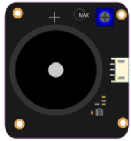
Image of FIT0449
Cirkit Designer LogoDesign with FIT0449 in Cirkit Designer

Introduction

The FIT0449 is a 12mm RGB (Red, Green, Blue) LED with a common anode configuration. This electronic component is capable of producing a wide spectrum of colors by mixing red, green, and blue light. It is commonly used in electronics projects for color indication, mood lighting, and lighting effects. The versatility of the FIT0449 makes it suitable for hobbyist projects, educational purposes, and even commercial applications.

Explore Projects Built with FIT0449

Use Cirkit Designer to design, explore, and prototype these projects online. Some projects support real-time simulation. Click "Open Project" to start designing instantly!
Cellular-Enabled IoT Device with Real-Time Clock and Power Management
Image of LRCM PHASE 2 BASIC: A project utilizing FIT0449 in a practical application
This circuit features a LilyGo-SIM7000G module for cellular communication and GPS functionality, interfaced with an RTC DS3231 for real-time clock capabilities. It includes voltage sensing through two voltage sensor modules, and uses an 8-channel opto-coupler for isolating different parts of the circuit. Power management is handled by a buck converter connected to a DC power source and batteries, with a fuse for protection and a rocker switch for on/off control. Additionally, there's an LED for indication purposes.
Cirkit Designer LogoOpen Project in Cirkit Designer
Battery-Powered Emergency Alert System with NUCLEO-F072RB, SIM800L, and GPS NEO 6M
Image of women safety: A project utilizing FIT0449 in a practical application
This circuit is an emergency alert system that uses a NUCLEO-F072RB microcontroller to send SMS alerts and make calls via a SIM800L GSM module, while obtaining location data from a GPS NEO 6M module. The system is powered by a Li-ion battery and includes a TP4056 module for battery charging and protection, with a rocker switch to control power to the microcontroller.
Cirkit Designer LogoOpen Project in Cirkit Designer
Satellite-Based Timing and Navigation System with SDR and Atomic Clock Synchronization
Image of GPS 시스템 측정 구성도_Confirm: A project utilizing FIT0449 in a practical application
This circuit appears to be a complex system involving power supply management, GPS and timing synchronization, and data communication. It includes a SI-TEX G1 Satellite Compass for GPS data, an XHTF1021 Atomic Rubidium Clock for precise timing, and Ettus USRP B200 units for software-defined radio communication. Power is supplied through various SMPS units and distributed via terminal blocks and DC jacks. Data communication is facilitated by Beelink MINI S12 N95 computers, RS232 splitters, and a 1000BASE-T Media Converter for network connectivity. RF Directional Couplers are used to interface antennas with the USRP units, and the entire system is likely contained within cases for protection and organization.
Cirkit Designer LogoOpen Project in Cirkit Designer
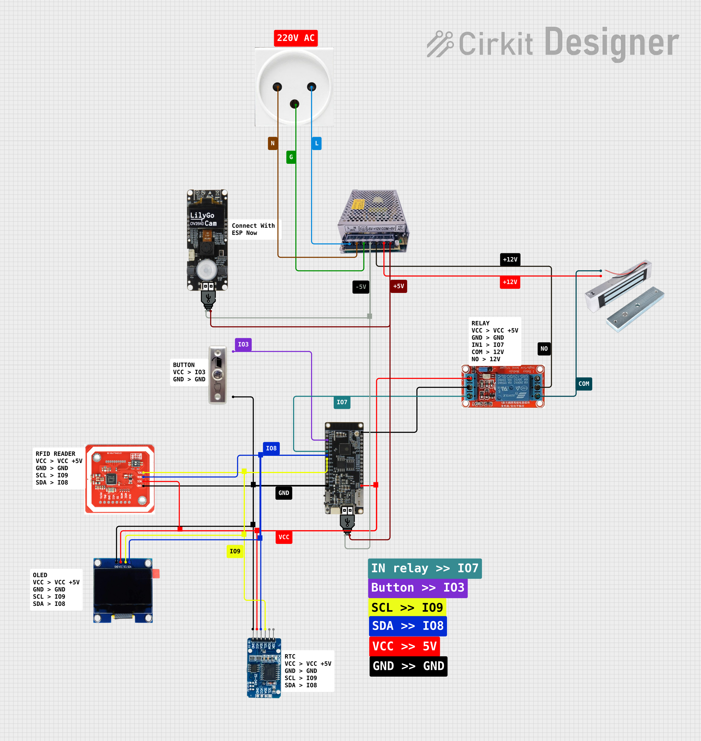
NFC-Enabled Access Control System with Time Logging
Image of doorlock: A project utilizing FIT0449 in a practical application
This circuit is designed for access control with time tracking capabilities. It features an NFC/RFID reader for authentication, an RTC module (DS3231) for real-time clock functionality, and an OLED display for user interaction. A 12V relay controls a magnetic lock, which is activated upon successful NFC/RFID authentication, and a button switch is likely used for manual operation or input. The T8_S3 microcontroller serves as the central processing unit, interfacing with the NFC/RFID reader, RTC, OLED, and relay to manage the access control logic.
Cirkit Designer LogoOpen Project in Cirkit Designer

Explore Projects Built with FIT0449

Use Cirkit Designer to design, explore, and prototype these projects online. Some projects support real-time simulation. Click "Open Project" to start designing instantly!
Image of LRCM PHASE 2 BASIC: A project utilizing FIT0449 in a practical application
Cellular-Enabled IoT Device with Real-Time Clock and Power Management
This circuit features a LilyGo-SIM7000G module for cellular communication and GPS functionality, interfaced with an RTC DS3231 for real-time clock capabilities. It includes voltage sensing through two voltage sensor modules, and uses an 8-channel opto-coupler for isolating different parts of the circuit. Power management is handled by a buck converter connected to a DC power source and batteries, with a fuse for protection and a rocker switch for on/off control. Additionally, there's an LED for indication purposes.
Cirkit Designer LogoOpen Project in Cirkit Designer
Image of women safety: A project utilizing FIT0449 in a practical application
Battery-Powered Emergency Alert System with NUCLEO-F072RB, SIM800L, and GPS NEO 6M
This circuit is an emergency alert system that uses a NUCLEO-F072RB microcontroller to send SMS alerts and make calls via a SIM800L GSM module, while obtaining location data from a GPS NEO 6M module. The system is powered by a Li-ion battery and includes a TP4056 module for battery charging and protection, with a rocker switch to control power to the microcontroller.
Cirkit Designer LogoOpen Project in Cirkit Designer
Image of GPS 시스템 측정 구성도_Confirm: A project utilizing FIT0449 in a practical application
Satellite-Based Timing and Navigation System with SDR and Atomic Clock Synchronization
This circuit appears to be a complex system involving power supply management, GPS and timing synchronization, and data communication. It includes a SI-TEX G1 Satellite Compass for GPS data, an XHTF1021 Atomic Rubidium Clock for precise timing, and Ettus USRP B200 units for software-defined radio communication. Power is supplied through various SMPS units and distributed via terminal blocks and DC jacks. Data communication is facilitated by Beelink MINI S12 N95 computers, RS232 splitters, and a 1000BASE-T Media Converter for network connectivity. RF Directional Couplers are used to interface antennas with the USRP units, and the entire system is likely contained within cases for protection and organization.
Cirkit Designer LogoOpen Project in Cirkit Designer
Image of doorlock: A project utilizing FIT0449 in a practical application
NFC-Enabled Access Control System with Time Logging
This circuit is designed for access control with time tracking capabilities. It features an NFC/RFID reader for authentication, an RTC module (DS3231) for real-time clock functionality, and an OLED display for user interaction. A 12V relay controls a magnetic lock, which is activated upon successful NFC/RFID authentication, and a button switch is likely used for manual operation or input. The T8_S3 microcontroller serves as the central processing unit, interfacing with the NFC/RFID reader, RTC, OLED, and relay to manage the access control logic.
Cirkit Designer LogoOpen Project in Cirkit Designer

Technical Specifications

General Features

  • Diameter: 12mm
  • Lens Type: Clear
  • Forward Voltage (typical):
    • Red: 1.8V to 2.2V
    • Green: 3.0V to 3.4V
    • Blue: 3.0V to 3.4V
  • Forward Current: 20mA (per channel)
  • Luminous Intensity:
    • Red: 500-700mcd
    • Green: 1100-1400mcd
    • Blue: 200-400mcd
  • Viewing Angle: 30 degrees

Pin Configuration

Pin Number Description
1 Red Anode
2 Green Anode
3 Blue Anode
4 Common Cathode

Usage Instructions

Connecting to a Circuit

To use the FIT0449 in a circuit, connect the common anode pin to a positive voltage supply and each of the RGB anodes to a current-limiting resistor before connecting to the ground or a microcontroller's GPIO pins. The value of the resistor will depend on the supply voltage and the desired current. Typically, a 220-ohm resistor is used for a 5V supply.

Best Practices

  • Always use current-limiting resistors to prevent damage to the LED.
  • Avoid exceeding the maximum forward current and voltage ratings.
  • Use pulse-width modulation (PWM) to control the brightness and color mixing.

Example Code for Arduino UNO

// Define the RGB LED pins
const int RED_PIN = 9;   // Red pin connected to digital pin 9
const int GREEN_PIN = 10; // Green pin connected to digital pin 10
const int BLUE_PIN = 11;  // Blue pin connected to digital pin 11

void setup() {
  // Set the LED pins as output
  pinMode(RED_PIN, OUTPUT);
  pinMode(GREEN_PIN, OUTPUT);
  pinMode(BLUE_PIN, OUTPUT);
}

void loop() {
  // Set the color to purple
  analogWrite(RED_PIN, 255);   // Red at full intensity
  analogWrite(GREEN_PIN, 0);   // Green off
  analogWrite(BLUE_PIN, 255);  // Blue at full intensity
  
  delay(1000); // Wait for 1 second
  
  // Set the color to aqua
  analogWrite(RED_PIN, 0);     // Red off
  analogWrite(GREEN_PIN, 255); // Green at full intensity
  analogWrite(BLUE_PIN, 255);  // Blue at full intensity
  
  delay(1000); // Wait for 1 second
}

Troubleshooting and FAQs

Common Issues

  • LED not lighting up: Ensure that the common anode is connected to a positive voltage and that each anode is connected through a current-limiting resistor to the ground.
  • Dim or uneven color output: Check that the resistors are of the correct value and that the supply voltage is adequate.
  • LED burned out: This can happen if the current-limiting resistor is omitted or if the voltage applied is too high.

FAQs

Q: Can I control the FIT0449 with a microcontroller? A: Yes, you can control the FIT0449 using a microcontroller like the Arduino UNO by using PWM on the RGB pins.

Q: What resistor value should I use? A: For a 5V supply, 220-ohm resistors are commonly used. Adjust the value based on your supply voltage and desired current.

Q: How do I create different colors? A: By adjusting the PWM signal to each of the RGB pins, you can mix colors to create a wide range of hues.

Q: Can I power the FIT0449 directly from an Arduino pin? A: Yes, but ensure that you do not exceed the maximum current rating of the Arduino pin and the LED.

Q: Is it possible to chain multiple FIT0449 LEDs together? A: Yes, you can chain them, but each LED will need its own set of current-limiting resistors, and you must ensure that the power supply can handle the total current draw.