How to Use BuckConverter12V: Examples, Pinouts, and Specs
Introduction
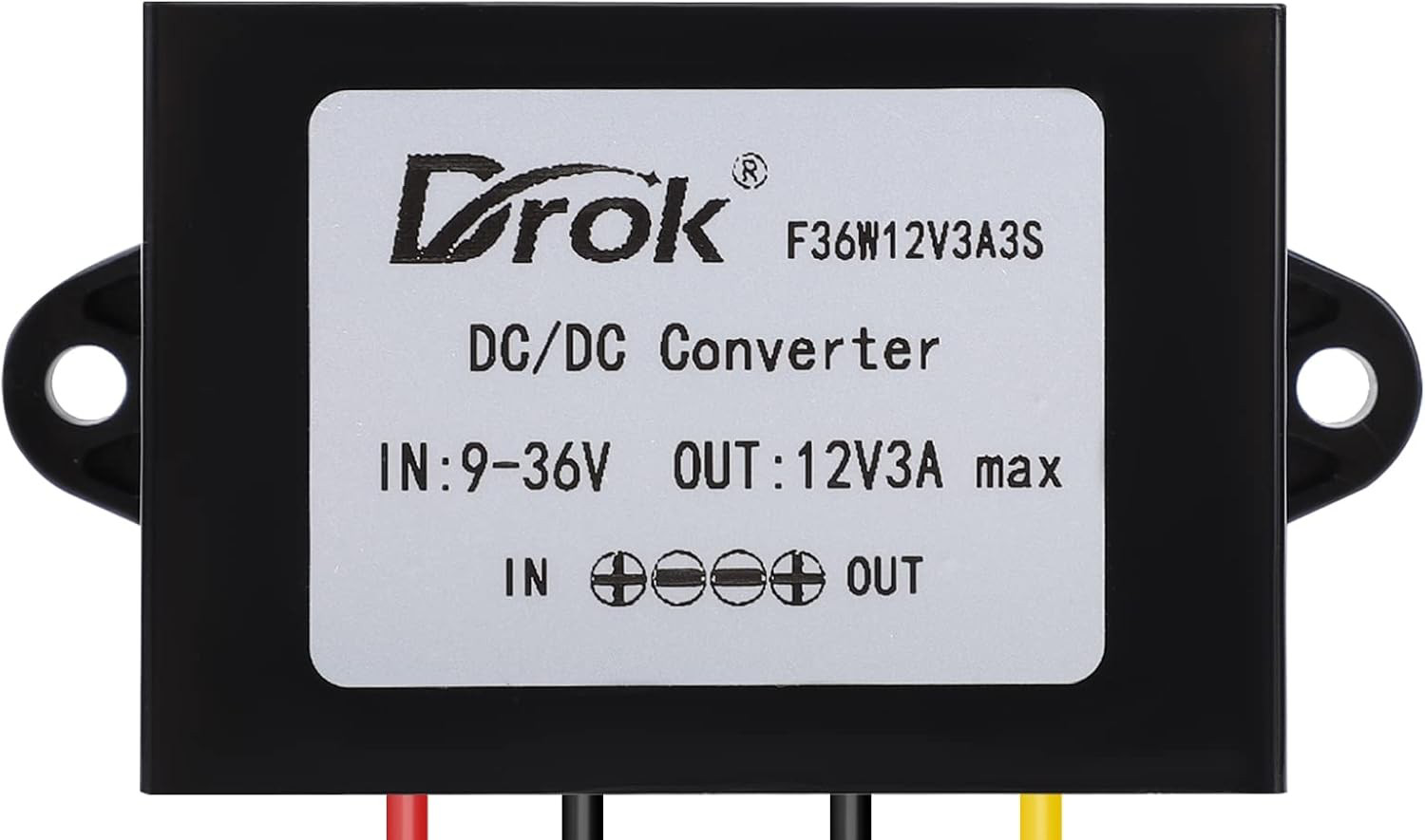
A Buck Converter is a type of DC-DC converter that steps down voltage from a higher level to a lower level while maintaining high efficiency. The BuckConverter12V is specifically designed to output a regulated 12 volts, making it ideal for powering devices that require a stable 12V supply from a higher voltage source, such as 24V or 48V systems.
Explore Projects Built with BuckConverter12V


Explore Projects Built with BuckConverter12V
Common Applications and Use Cases
- Powering 12V devices (e.g., LED strips, fans, and sensors) from higher voltage sources.
- Battery-powered systems where voltage regulation is required.
- Automotive applications to step down voltage from a car battery (e.g., 24V to 12V).
- Industrial equipment requiring a stable 12V power supply.
- DIY electronics projects and prototyping.
Technical Specifications
Key Technical Details
| Parameter | Value |
|---|---|
| Input Voltage Range | 15V to 40V |
| Output Voltage | 12V (regulated) |
| Output Current | Up to 5A |
| Efficiency | Up to 95% (depending on load) |
| Switching Frequency | 150 kHz |
| Operating Temperature | -40°C to +85°C |
| Dimensions | 45mm x 25mm x 15mm |
Pin Configuration and Descriptions
| Pin Name | Description |
|---|---|
| VIN+ | Positive input voltage terminal (connect to the higher voltage source). |
| VIN- | Negative input voltage terminal (connect to the ground of the source). |
| VOUT+ | Positive output voltage terminal (provides regulated 12V output). |
| VOUT- | Negative output voltage terminal (connect to the ground of the load). |
| EN (optional) | Enable pin (used to turn the converter on/off; active high). |
Usage Instructions
How to Use the BuckConverter12V in a Circuit
Connect the Input Voltage:
- Connect the VIN+ pin to the positive terminal of your input voltage source (e.g., 24V).
- Connect the VIN- pin to the ground of your input voltage source.
- Ensure the input voltage is within the specified range (15V to 40V).
Connect the Output Voltage:
- Connect the VOUT+ pin to the positive terminal of your load (e.g., a 12V device).
- Connect the VOUT- pin to the ground of your load.
Enable the Converter (if applicable):
- If the module has an EN (Enable) pin, connect it to a HIGH signal (e.g., 5V) to activate the converter.
- Leave the EN pin unconnected or pull it LOW to disable the converter.
Power On:
- Turn on the input voltage source. The BuckConverter12V will regulate the input voltage and provide a stable 12V output.
Important Considerations and Best Practices
- Input Voltage Range: Ensure the input voltage is always within the specified range (15V to 40V). Exceeding this range may damage the converter.
- Heat Dissipation: At high loads, the converter may generate heat. Use a heatsink or ensure proper ventilation to prevent overheating.
- Load Requirements: Do not exceed the maximum output current of 5A. Overloading the converter may cause it to shut down or fail.
- Polarity: Double-check the polarity of your connections. Reversing the input or output connections can damage the module.
- Filtering: For sensitive applications, consider adding input and output capacitors to reduce noise and ripple.
Example: Using BuckConverter12V with Arduino UNO
The BuckConverter12V can be used to power an Arduino UNO from a 24V source. Here's how to connect it:
- Connect the VIN+ and VIN- pins of the BuckConverter12V to the 24V source.
- Connect the VOUT+ pin to the Arduino's VIN pin.
- Connect the VOUT- pin to the Arduino's GND pin.
Sample Arduino Code
// Example code to blink an LED connected to pin 13 of the Arduino UNO
// Ensure the Arduino is powered via the BuckConverter12V module.

void setup() {
  pinMode(13, OUTPUT); // Set pin 13 as an output
}

void loop() {
  digitalWrite(13, HIGH); // Turn the LED on
  delay(1000);            // Wait for 1 second
  digitalWrite(13, LOW);  // Turn the LED off
  delay(1000);            // Wait for 1 second
}
Troubleshooting and FAQs
Common Issues and Solutions
| Issue | Possible Cause | Solution |
|---|---|---|
| No output voltage | Input voltage is too low or disconnected | Ensure input voltage is within 15V-40V. |
| Output voltage is unstable | Insufficient input filtering | Add input capacitors (e.g., 100µF). |
| Module overheats | Excessive load or poor ventilation | Reduce load or add a heatsink. |
| Device does not power on | EN pin is not connected or is LOW | Connect EN pin to a HIGH signal (e.g., 5V). |
| Output voltage is not 12V | Faulty module or incorrect connections | Verify connections and replace module if needed. |
FAQs
Q1: Can I use the BuckConverter12V to power a Raspberry Pi?
A1: Yes, as long as the Raspberry Pi's power requirements (voltage and current) are within the module's output specifications.
Q2: What happens if I exceed the maximum input voltage?
A2: Exceeding the input voltage range (40V) can permanently damage the module. Always use a voltage source within the specified range.
Q3: Can I adjust the output voltage?
A3: No, the BuckConverter12V is designed to provide a fixed 12V output. For adjustable output, consider using a different buck converter model.
Q4: Is the module protected against short circuits?
A4: Many BuckConverter12V modules include short-circuit protection, but it is recommended to check the specific datasheet for your module.
Q5: Can I use this module in parallel with another BuckConverter12V?
A5: It is not recommended to connect multiple modules in parallel unless specifically designed for such use, as it may cause instability.
This concludes the documentation for the BuckConverter12V.