How to Use Speed Motor Controller: Examples, Pinouts, and Specs
Introduction
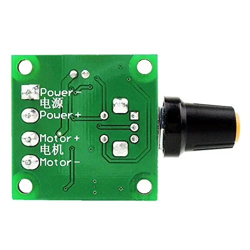
A Speed Motor Controller is a device used to regulate the speed of an electric motor by adjusting the voltage or current supplied to it. This component is essential in applications where precise motor speed control is required, such as in robotics, conveyor belts, electric vehicles, and industrial machinery. By varying the power delivered to the motor, the controller ensures smooth operation and efficient performance.
Common applications and use cases include:
- Robotics for controlling wheel or arm movement
- Electric vehicles for speed regulation
- Industrial automation systems
- Fans, pumps, and conveyor belts
- DIY projects involving motorized systems
Explore Projects Built with Speed Motor Controller

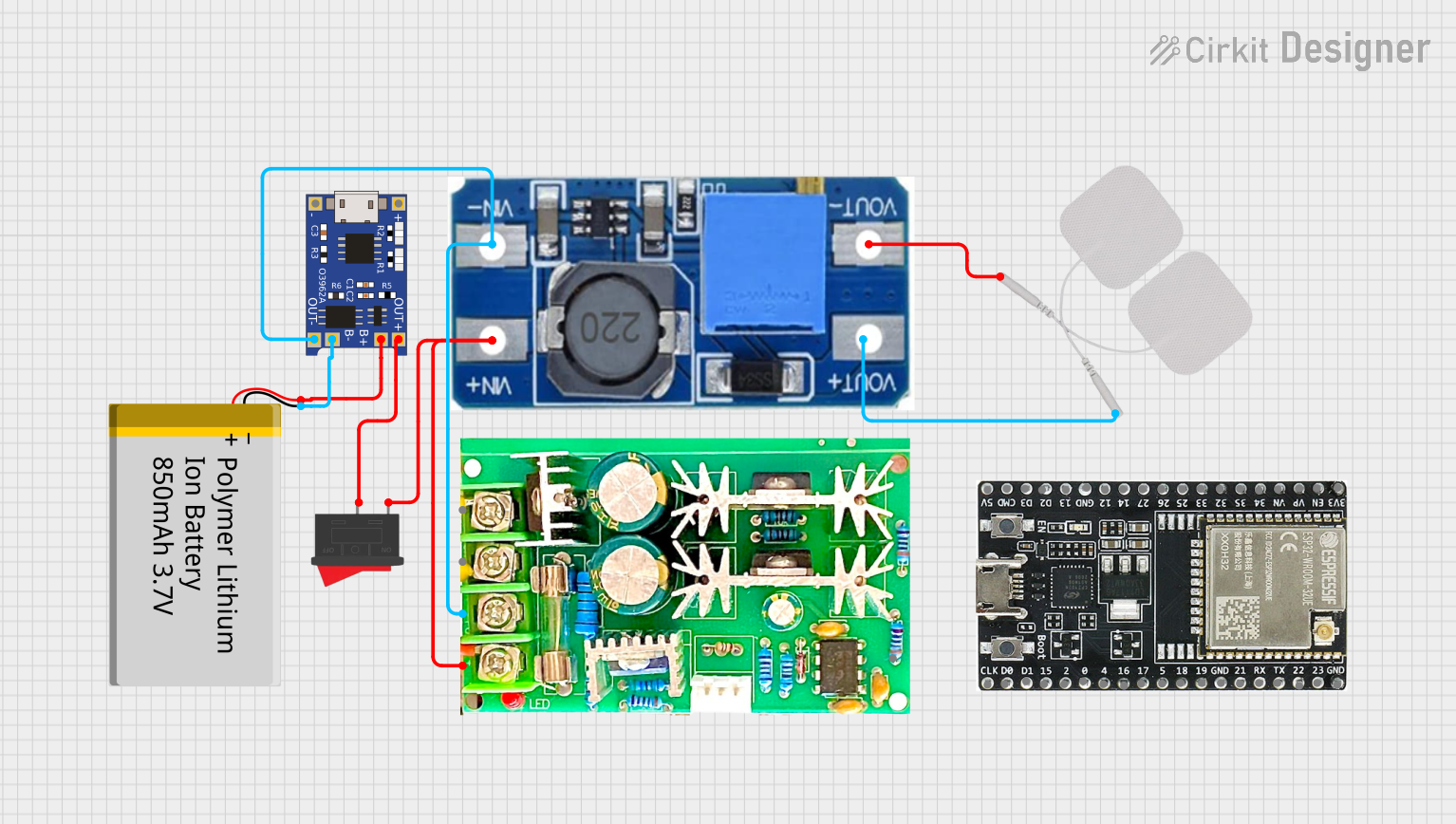
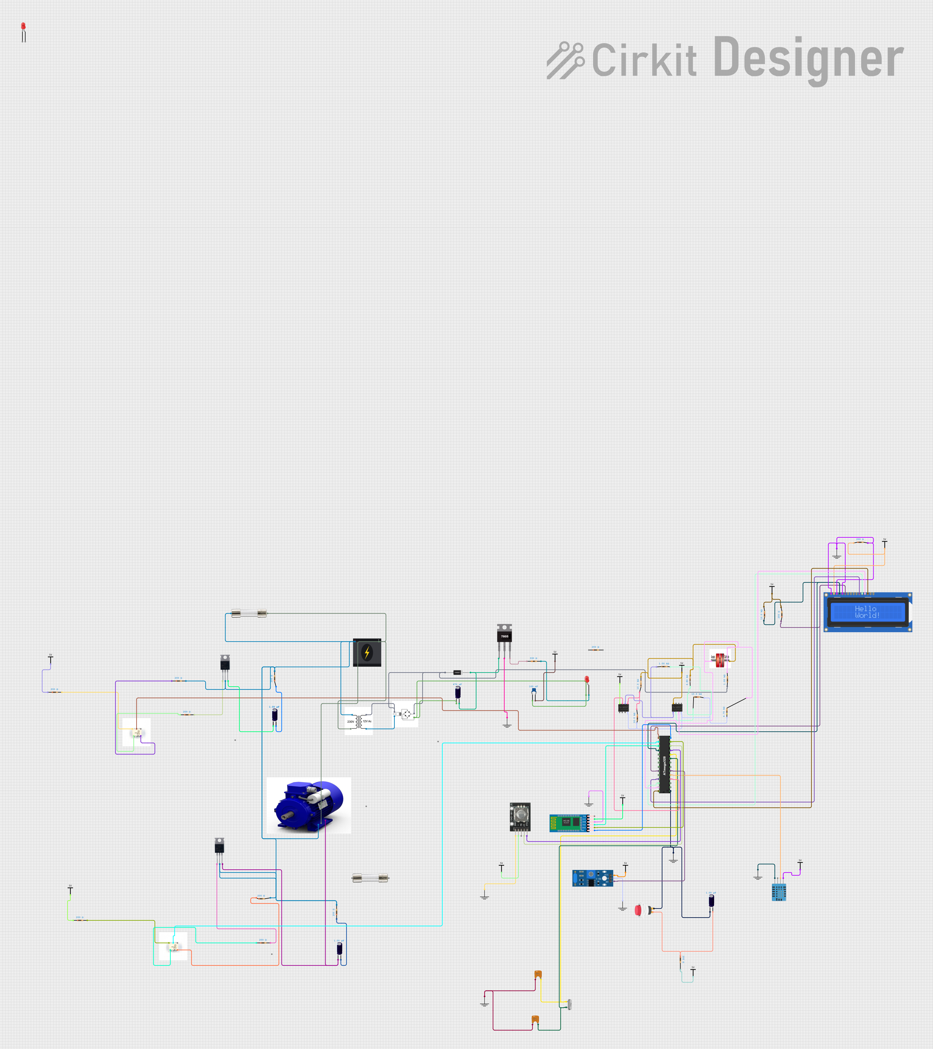
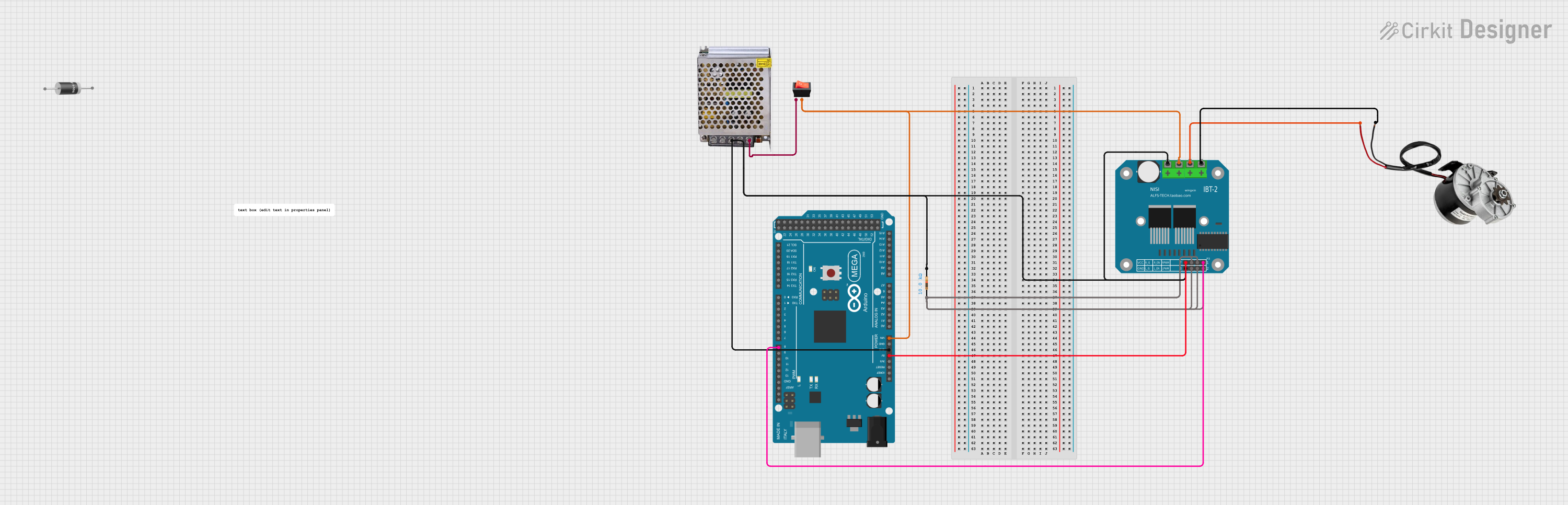
Explore Projects Built with Speed Motor Controller
Technical Specifications
Below are the key technical details for a typical Speed Motor Controller:
| Parameter | Value |
|---|---|
| Input Voltage Range | 6V to 30V DC |
| Output Current | Up to 10A (varies by model) |
| Control Signal Type | PWM (Pulse Width Modulation) |
| PWM Frequency Range | 1 kHz to 20 kHz |
| Efficiency | Up to 95% |
| Operating Temperature | -20°C to 85°C |
| Protection Features | Overcurrent, Overvoltage, Thermal |
Pin Configuration and Descriptions
The pin configuration for a typical Speed Motor Controller is as follows:
| Pin Name | Description |
|---|---|
| VIN | Positive input voltage terminal |
| GND | Ground terminal |
| OUT+ | Positive output terminal to the motor |
| OUT- | Negative output terminal to the motor |
| PWM | PWM input signal for speed control |
| EN | Enable pin to turn the motor on/off (optional) |
Usage Instructions
How to Use the Component in a Circuit
- Connect the Power Supply: Attach the positive terminal of the power supply to the
VINpin and the negative terminal to theGNDpin. Ensure the voltage is within the specified range. - Connect the Motor: Connect the motor terminals to the
OUT+andOUT-pins of the controller. - Provide a PWM Signal: Use a microcontroller (e.g., Arduino UNO) or a signal generator to send a PWM signal to the
PWMpin. The duty cycle of the PWM signal determines the motor speed. - Enable the Controller: If the controller has an
ENpin, set it to HIGH to enable the motor. Setting it to LOW will disable the motor.
Important Considerations and Best Practices
- Power Supply: Ensure the power supply can provide sufficient current for the motor and the controller.
- Heat Dissipation: For high-current applications, use a heatsink or active cooling to prevent overheating.
- PWM Frequency: Choose an appropriate PWM frequency to avoid audible noise and ensure smooth motor operation.
- Reverse Polarity Protection: Verify the polarity of the connections to avoid damaging the controller.
- Isolation: If controlling high-power motors, consider using optocouplers or isolation circuits to protect the microcontroller.
Example: Using with Arduino UNO
Below is an example of how to control a motor's speed using an Arduino UNO and a Speed Motor Controller:
// Define the PWM pin connected to the motor controller
const int pwmPin = 9; // Pin 9 on Arduino UNO

void setup() {
  pinMode(pwmPin, OUTPUT); // Set the PWM pin as an output
}

void loop() {
  // Gradually increase motor speed
  for (int speed = 0; speed <= 255; speed++) {
    analogWrite(pwmPin, speed); // Write PWM signal to the controller
    delay(20); // Wait 20ms before increasing speed
  }

  // Gradually decrease motor speed
  for (int speed = 255; speed >= 0; speed--) {
    analogWrite(pwmPin, speed); // Write PWM signal to the controller
    delay(20); // Wait 20ms before decreasing speed
  }
}
Troubleshooting and FAQs
Common Issues and Solutions
Motor Does Not Spin:
- Check the power supply voltage and current ratings.
- Verify all connections, especially the motor and power supply terminals.
- Ensure the
ENpin is set to HIGH (if applicable).
Motor Spins Erratically:
- Check the PWM signal for noise or incorrect frequency.
- Ensure the motor is not overloaded or mechanically obstructed.
Controller Overheats:
- Reduce the motor load or use a heatsink for better heat dissipation.
- Verify that the input voltage and current are within the specified range.
No Response to PWM Signal:
- Confirm the PWM pin is correctly connected to the controller.
- Check the microcontroller code for errors or incorrect pin assignments.
FAQs
Q: Can I use the Speed Motor Controller with an AC motor?
A: No, this controller is designed for DC motors only. For AC motors, use a variable frequency drive (VFD).
Q: What happens if I reverse the power supply polarity?
A: Most controllers include reverse polarity protection, but it is best to double-check connections to avoid potential damage.
Q: Can I control multiple motors with one controller?
A: No, each motor requires its own controller to ensure proper operation and avoid overloading.
Q: What is the ideal PWM frequency for motor control?
A: A frequency between 1 kHz and 20 kHz is typically suitable. Higher frequencies reduce audible noise but may increase heat generation.