How to Use STM32F103C8T6: Examples, Pinouts, and Specs
Introduction
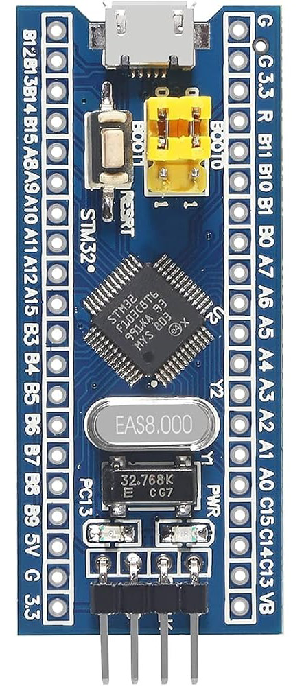
The STM32F103C8T6, commonly referred to as the "Blue Pill," is a versatile and cost-effective microcontroller unit (MCU) from STMicroelectronics. Based on the ARM Cortex-M3 processor, it offers a balanced combination of performance, power consumption, and peripherals. This MCU is widely used in a range of applications, including industrial control systems, medical devices, consumer electronics, and Internet of Things (IoT) devices.
Explore Projects Built with STM32F103C8T6

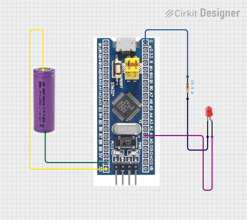

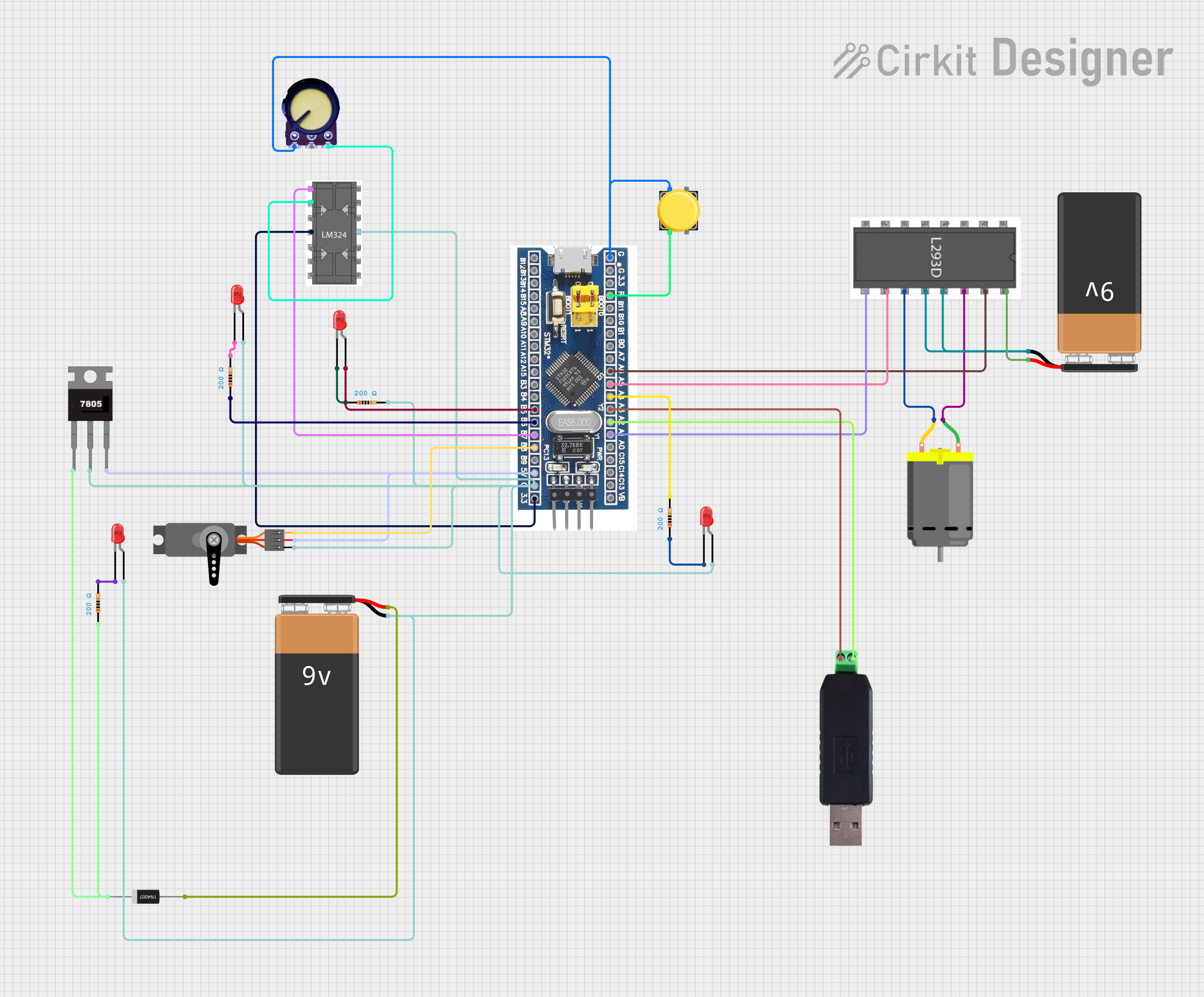
Explore Projects Built with STM32F103C8T6
Technical Specifications
Key Features
- Core: ARM Cortex-M3 32-bit RISC
- Operating Voltage: 2.0 to 3.6 V
- Max Frequency: 72 MHz
- Flash Memory: 64 KB
- SRAM: 20 KB
- Debugging: SWD (Serial Wire Debug)
Pin Configuration and Descriptions
| Pin Number | Pin Name | Function(s) |
|---|---|---|
| 1 | VBAT | Battery input for RTC |
| 2-15 | PA0-PA15 | GPIO/ADC/USART/Timer |
| 16-30 | PB0-PB15 | GPIO/ADC/USART/Timer |
| 31 | BOOT0 | Boot configuration |
| 32-37 | PC13-PC15, PD0-PD2 | GPIO/RTC |
| ... | ... | ... |
| 64 | VSS | Ground |
Note: This table is not exhaustive. Refer to the datasheet for the complete pinout and alternate functions.
Usage Instructions
Integration into a Circuit
- Power Supply: Ensure that the power supply is within the specified range (2.0 to 3.6 V). Exceeding this range can damage the MCU.
- Decoupling Capacitors: Place a 100 nF ceramic capacitor close to the VDD pins to filter out noise.
- Boot Configuration: The BOOT0 pin determines the boot space. Connect to GND for normal operation or VDD for system memory boot.
Programming
- IDE Support: The STM32F103C8T6 is supported by various development environments, including the STM32CubeIDE and Arduino IDE with an additional core.
- Flashing: Use an ST-Link/V2 programmer/debugger or a USB-to-serial adapter for programming via the bootloader.
Best Practices
- ESD Precautions: Always follow electrostatic discharge (ESD) precautions when handling the MCU to prevent damage.
- I/O Pin Limits: Do not exceed the maximum current and voltage levels on I/O pins to avoid permanent damage.
Example Code for Arduino UNO
#include <STM32F1xx.h>

void setup() {
  // Initialize a GPIO pin
  pinMode(PA0, OUTPUT);
}

void loop() {
  // Toggle the GPIO pin
  digitalWrite(PA0, HIGH);
  delay(1000);
  digitalWrite(PA0, LOW);
  delay(1000);
}
Note: This example assumes you have installed the necessary STM32 core in the Arduino IDE.
Troubleshooting and FAQs
Common Issues
- MCU Not Responding: Ensure that the power supply is correctly connected and within the specified range. Check for proper boot configuration.
- Programming Errors: Verify connections to the programmer/debugger and ensure that the correct drivers are installed.
FAQs
Q: Can I program the STM32F103C8T6 using the Arduino IDE? A: Yes, by installing the STM32 core for Arduino, you can program the Blue Pill using the Arduino IDE.
Q: What is the maximum operating temperature of the STM32F103C8T6? A: The maximum operating temperature is typically 85°C. Refer to the datasheet for detailed thermal specifications.
Q: How can I reset the MCU? A: The MCU can be reset by pulling the NRST pin low.
For more detailed troubleshooting, consult the STM32F103C8T6 datasheet and reference manual provided by STMicroelectronics.