Cirkit Designer Logo
Cirkit Designer
Your all-in-one circuit design IDE
Home / 
Component Documentation

How to Use DKC-1A(Stepper_Motor_Controllers): Examples, Pinouts, and Specs

Image of DKC-1A(Stepper_Motor_Controllers)
Cirkit Designer LogoDesign with DKC-1A(Stepper_Motor_Controllers) in Cirkit Designer

Introduction

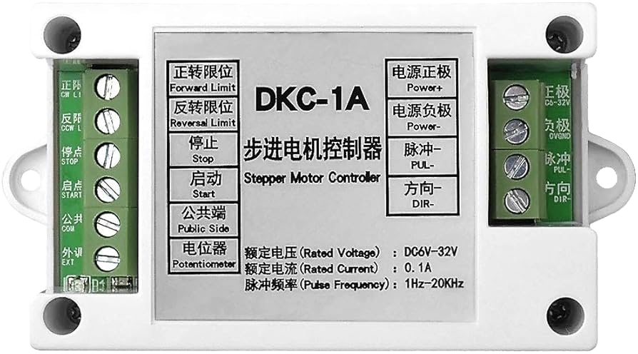
The DKC-1A Stepper Motor Controller is a versatile and reliable electronic device designed to drive stepper motors with precision and ease. Stepper motors are commonly used in applications requiring controlled, precise movements such as 3D printers, CNC machines, robotics, and automated manufacturing systems. The DKC-1A controller allows users to command a stepper motor to move to specific positions or at certain speeds without the need for constant feedback about the motor's position.

Explore Projects Built with DKC-1A(Stepper_Motor_Controllers)

Use Cirkit Designer to design, explore, and prototype these projects online. Some projects support real-time simulation. Click "Open Project" to start designing instantly!
Stepper Motor Control System with TB6600 Driver and DKC-1A Controller
Image of Copy of Copy of PLC-Based Step Motor Speed and Direction Control System: A project utilizing DKC-1A(Stepper_Motor_Controllers) in a practical application
This circuit controls a bipolar stepper motor using a tb6600 micro stepping motor driver and a DKC-1A stepper motor controller. The system is powered by a 24VDC power supply and includes a relay module for additional control functionalities.
Cirkit Designer LogoOpen Project in Cirkit Designer
Stepper Motor Control System with SIMATIC S7-300 and TB6600 Driver
Image of Copy of PLC-Based Step Motor Speed and Direction Control System: A project utilizing DKC-1A(Stepper_Motor_Controllers) in a practical application
This circuit controls a stepper motor using a tb6600 micro stepping motor driver and a DKC-1A stepper motor controller. The system is powered through panel mount banana sockets and includes a relay module for additional control, interfaced with a SIMATIC S7-300 PLC for automation.
Cirkit Designer LogoOpen Project in Cirkit Designer
Stepper Motor Control System with TB6600 Driver and Relay Integration
Image of Copy of Copy of Copy of PLC-Based Step Motor Speed and Direction Control System: A project utilizing DKC-1A(Stepper_Motor_Controllers) in a practical application
This circuit controls a bipolar stepper motor using a tb6600 micro stepping motor driver and a DKC-1A stepper motor controller. It includes a 24VDC power supply, a 4-channel relay module, and panel mount banana sockets for power connections. The motor driver and controller are interconnected to manage the motor's direction and pulse signals.
Cirkit Designer LogoOpen Project in Cirkit Designer
Arduino Mega 2560 Stepper Motor Controller with LCD Display and Keypad
Image of Stepper-encoder-LCD-keyboard: A project utilizing DKC-1A(Stepper_Motor_Controllers) in a practical application
This circuit controls a stepper motor using an Arduino Mega 2560, a DM542T driver, an LCD display, a membrane keypad, and a rotary encoder. The user can set and fine-tune the rotation angle and speed of the stepper motor via the keypad and rotary encoder, with the current settings displayed on the LCD.
Cirkit Designer LogoOpen Project in Cirkit Designer

Explore Projects Built with DKC-1A(Stepper_Motor_Controllers)

Use Cirkit Designer to design, explore, and prototype these projects online. Some projects support real-time simulation. Click "Open Project" to start designing instantly!
Image of Copy of Copy of PLC-Based Step Motor Speed and Direction Control System: A project utilizing DKC-1A(Stepper_Motor_Controllers) in a practical application
Stepper Motor Control System with TB6600 Driver and DKC-1A Controller
This circuit controls a bipolar stepper motor using a tb6600 micro stepping motor driver and a DKC-1A stepper motor controller. The system is powered by a 24VDC power supply and includes a relay module for additional control functionalities.
Cirkit Designer LogoOpen Project in Cirkit Designer
Image of Copy of PLC-Based Step Motor Speed and Direction Control System: A project utilizing DKC-1A(Stepper_Motor_Controllers) in a practical application
Stepper Motor Control System with SIMATIC S7-300 and TB6600 Driver
This circuit controls a stepper motor using a tb6600 micro stepping motor driver and a DKC-1A stepper motor controller. The system is powered through panel mount banana sockets and includes a relay module for additional control, interfaced with a SIMATIC S7-300 PLC for automation.
Cirkit Designer LogoOpen Project in Cirkit Designer
Image of Copy of Copy of Copy of PLC-Based Step Motor Speed and Direction Control System: A project utilizing DKC-1A(Stepper_Motor_Controllers) in a practical application
Stepper Motor Control System with TB6600 Driver and Relay Integration
This circuit controls a bipolar stepper motor using a tb6600 micro stepping motor driver and a DKC-1A stepper motor controller. It includes a 24VDC power supply, a 4-channel relay module, and panel mount banana sockets for power connections. The motor driver and controller are interconnected to manage the motor's direction and pulse signals.
Cirkit Designer LogoOpen Project in Cirkit Designer
Image of Stepper-encoder-LCD-keyboard: A project utilizing DKC-1A(Stepper_Motor_Controllers) in a practical application
Arduino Mega 2560 Stepper Motor Controller with LCD Display and Keypad
This circuit controls a stepper motor using an Arduino Mega 2560, a DM542T driver, an LCD display, a membrane keypad, and a rotary encoder. The user can set and fine-tune the rotation angle and speed of the stepper motor via the keypad and rotary encoder, with the current settings displayed on the LCD.
Cirkit Designer LogoOpen Project in Cirkit Designer

Technical Specifications

Key Technical Details

  • Operating Voltage: 12-24V DC
  • Output Current: Adjustable up to 3A per phase
  • Microstepping: Full, 1/2, 1/4, 1/8, 1/16 steps
  • Input Signal Voltage: 5V (TTL compatible)
  • Control Method: Step and Direction
  • Dimensions: 75mm x 50mm x 35mm (L x W x H)

Pin Configuration and Descriptions

Pin Number Name Description
1 VDD Logic supply voltage (5V)
2 GND Ground connection
3 PUL+ Pulse signal input: controls step rate
4 PUL- Pulse signal ground
5 DIR+ Direction signal input
6 DIR- Direction signal ground
7 ENA+ Enable motor output
8 ENA- Enable signal ground

Usage Instructions

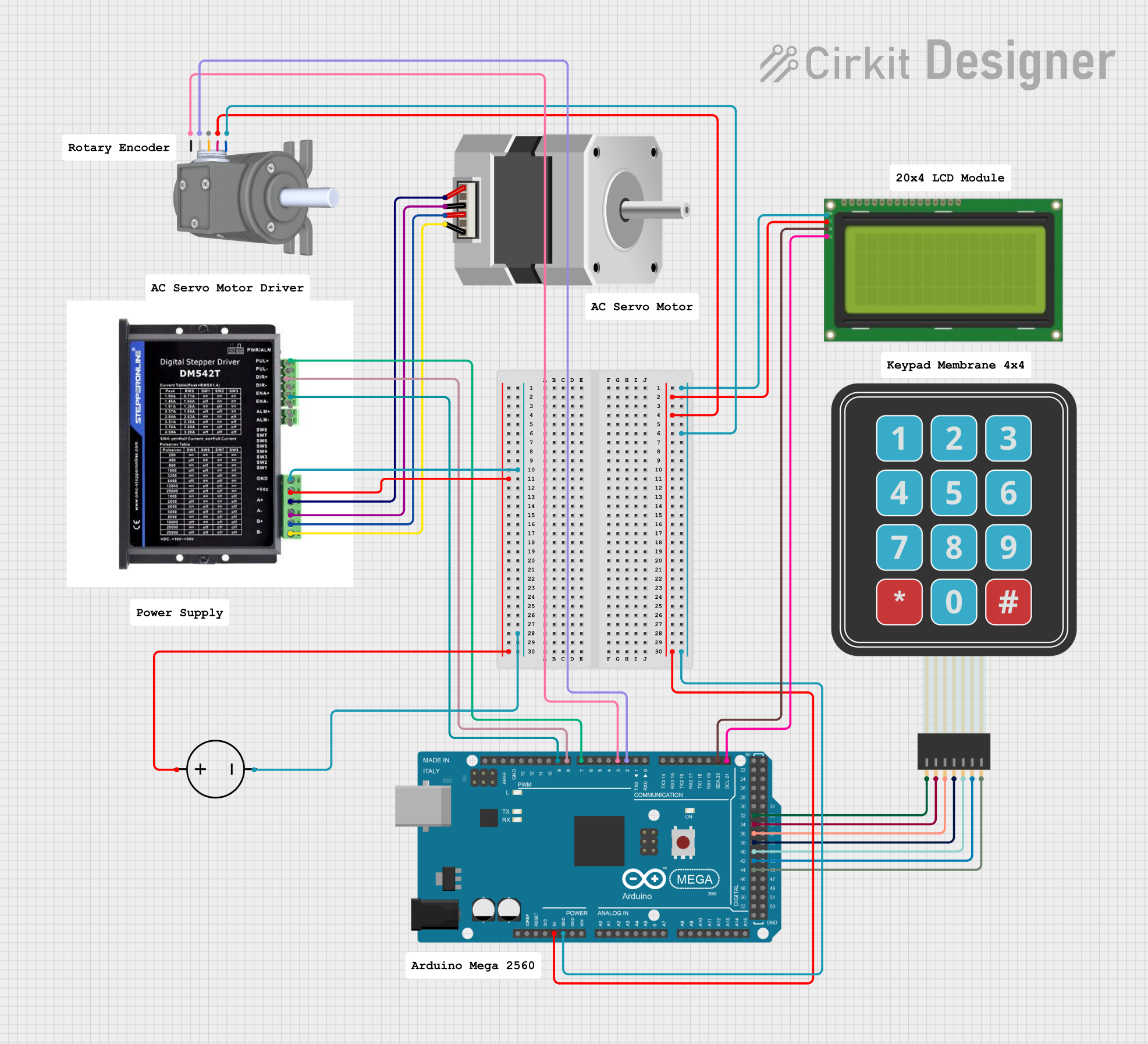
Connecting the DKC-1A to a Stepper Motor

  1. Power Supply: Connect a 12-24V DC power supply to the motor power inputs on the DKC-1A.
  2. Motor Connections: Connect the stepper motor wires to the appropriate outputs on the DKC-1A, ensuring correct phase alignment.
  3. Control Signals: Connect the PUL+, PUL-, DIR+, DIR-, ENA+, and ENA- to the control signals from your microcontroller or pulse generator.

Best Practices

  • Always ensure the power supply is turned off before making any connections.
  • Use a current limit setting appropriate for your stepper motor to prevent overheating.
  • For optimal performance, use shielded cables for control signals to minimize electrical noise.
  • Configure microstepping settings according to the precision required for your application.

Example Code for Arduino UNO

// Define the connections to the Arduino
const int dirPin = 2; // DIR+ to digital pin 2
const int stepPin = 3; // PUL+ to digital pin 3
const int enablePin = 4; // ENA+ to digital pin 4

void setup() {
  // Set the pin modes
  pinMode(dirPin, OUTPUT);
  pinMode(stepPin, OUTPUT);
  pinMode(enablePin, OUTPUT);

  // Enable the motor
  digitalWrite(enablePin, LOW);
}

void loop() {
  // Set the direction
  digitalWrite(dirPin, HIGH); // Set to LOW to change direction

  // Move the motor with a simple square wave
  digitalWrite(stepPin, HIGH);
  delayMicroseconds(500); // Set the speed with delay duration
  digitalWrite(stepPin, LOW);
  delayMicroseconds(500);
}

Troubleshooting and FAQs

Common Issues

  • Motor does not move: Check power supply and connections. Ensure the enable pin is set to the correct state.
  • Erratic movement: Verify that the control signals are not affected by noise. Use shorter cables or shielded wires.
  • Overheating: Ensure the current limit is set correctly for your motor. Provide adequate cooling if necessary.

FAQs

Q: Can I use the DKC-1A with a 5V stepper motor? A: No, the DKC-1A is designed for 12-24V motors. Using a 5V motor may damage the controller or the motor.

Q: How do I change the microstepping settings? A: Microstepping is typically set by DIP switches or jumpers on the controller board. Refer to the specific product manual for details.

Q: What is the maximum stepping frequency for the DKC-1A? A: The maximum stepping frequency depends on the motor and power supply, but the controller can typically handle up to several kHz.

Remember to always refer to the DKC-1A Stepper Motor Controller's manual for detailed information and safety guidelines.