How to Use Thermal Overload Relay (TOR): Examples, Pinouts, and Specs
Introduction
A Thermal Overload Relay (TOR) is a protective device designed to safeguard electric motors from overheating caused by excessive current. It operates by interrupting the power supply to the motor when an overload condition is detected, preventing potential damage to the motor and associated equipment. TORs are widely used in industrial and commercial applications where electric motors are critical to operations.
Explore Projects Built with Thermal Overload Relay (TOR)


Explore Projects Built with Thermal Overload Relay (TOR)
Common Applications and Use Cases
- Protection of electric motors in industrial machinery
- HVAC systems to prevent motor burnout
- Conveyor systems and pumps
- Compressors and fans
- Any application requiring motor overload protection
Technical Specifications
Key Technical Details
- Operating Voltage Range: Typically 24V to 690V AC (varies by model)
- Current Rating: Adjustable, typically from 0.1A to 630A
- Trip Class: Commonly Class 10, 20, or 30 (defines trip time under overload)
- Reset Mechanism: Manual or automatic
- Contact Configuration: Normally Closed (NC) for overload trip, Normally Open (NO) for auxiliary signaling
- Ambient Temperature Compensation: -20°C to +60°C
- Mounting: Direct mounting on contactors or standalone
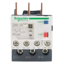
Pin Configuration and Descriptions
Thermal Overload Relays typically have terminals for power connections, auxiliary signaling, and reset functionality. Below is a general pin configuration:
| Pin/Terminal | Description |
|---|---|
| L1, L2, L3 | Line terminals for connecting the three-phase power supply |
| T1, T2, T3 | Load terminals for connecting to the motor |
| 95-96 | Normally Closed (NC) contact for overload trip (used to interrupt the circuit) |
| 97-98 | Normally Open (NO) auxiliary contact for signaling or alarms |
| Reset Button | Manual reset button to restore operation after a trip |
Note: The exact terminal labeling may vary depending on the manufacturer. Always refer to the datasheet for your specific model.
Usage Instructions
How to Use the Component in a Circuit
Determine the Motor's Full Load Current (FLC):
- Check the motor's nameplate for its rated full load current.
- Select a TOR with an adjustable current range that includes the motor's FLC.
Connect the TOR:
- Wire the line terminals (L1, L2, L3) to the power supply.
- Connect the load terminals (T1, T2, T3) to the motor.
- Use the NC contact (95-96) to interrupt the motor's control circuit in case of an overload.
- Optionally, connect the NO contact (97-98) to an alarm or indicator for signaling.
Adjust the Current Setting:
- Set the TOR's current adjustment dial to match the motor's FLC.
Test the Setup:
- Simulate an overload condition to ensure the TOR trips and interrupts the circuit.
Reset After Trip:
- If the TOR trips, allow the motor to cool down, then press the reset button (if manual reset is used).
Important Considerations and Best Practices
- Ambient Temperature Compensation: Ensure the TOR is rated for the operating environment's temperature range.
- Coordination with Contactors: Use a TOR that is compatible with the contactor controlling the motor.
- Regular Maintenance: Periodically inspect the TOR for signs of wear or damage.
- Avoid Nuisance Tripping: Set the current adjustment accurately to prevent unnecessary trips.
Example: Connecting a TOR to an Arduino UNO
While TORs are not typically controlled by microcontrollers like Arduino, you can use the auxiliary NO contact (97-98) to monitor the trip status. Below is an example of how to read the trip status using an Arduino UNO:
// Define the pin connected to the TOR's NO auxiliary contact
const int torAuxPin = 2; // Digital pin 2

void setup() {
  pinMode(torAuxPin, INPUT_PULLUP); // Set the pin as input with pull-up resistor
  Serial.begin(9600); // Initialize serial communication
}

void loop() {
  int torStatus = digitalRead(torAuxPin); // Read the TOR status

  if (torStatus == HIGH) {
    // NO contact is open, indicating no trip
    Serial.println("Motor is operating normally.");
  } else {
    // NO contact is closed, indicating a trip
    Serial.println("Thermal Overload Relay has tripped!");
  }

  delay(1000); // Wait for 1 second before checking again
}
Note: Ensure the auxiliary contact is connected to the Arduino with proper isolation (e.g., optocoupler) if the TOR operates at high voltage.
Troubleshooting and FAQs
Common Issues and Solutions
TOR Trips Frequently:
- Cause: Incorrect current setting or motor overload.
- Solution: Verify the motor's FLC and adjust the TOR's current setting accordingly. Check for mechanical issues causing the motor to draw excessive current.
Motor Does Not Start After Trip:
- Cause: Manual reset not performed or TOR still detecting overload.
- Solution: Press the reset button and ensure the motor has cooled down before restarting.
Nuisance Tripping in Cold Environments:
- Cause: Ambient temperature affecting the TOR's operation.
- Solution: Use a TOR with ambient temperature compensation or adjust the setting slightly higher.
No Signal from Auxiliary Contact:
- Cause: Faulty wiring or damaged contact.
- Solution: Inspect the wiring and test the auxiliary contact for continuity.
FAQs
Q: Can a TOR protect against short circuits?
A: No, a TOR is designed to protect against overloads, not short circuits. Use a circuit breaker or fuse for short-circuit protection.Q: How do I know if my TOR is compatible with my motor?
A: Check the TOR's current range, voltage rating, and trip class to ensure they match the motor's specifications.Q: Can I use a TOR with a single-phase motor?
A: Yes, but ensure the TOR is designed for single-phase operation or connect only two phases of a three-phase TOR.Q: What is the difference between manual and automatic reset?
A: Manual reset requires pressing a button to restore operation after a trip, while automatic reset restores operation automatically once the motor cools down.
By following this documentation, you can effectively use a Thermal Overload Relay to protect your electric motors and ensure reliable operation.