How to Use TP4056 + MT3608 Charger Module Step Up: Examples, Pinouts, and Specs
Introduction
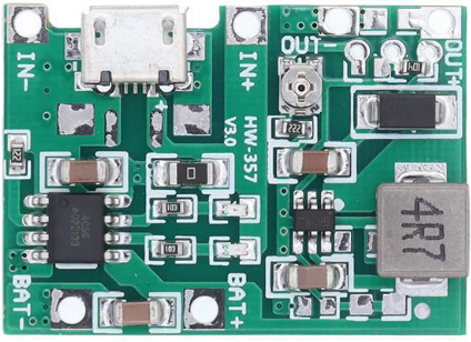
The TP4056 + MT3608 Charger Module Step Up (Manufacturer Part ID: Module-A87) is a versatile electronic module designed by Shenzhen KWM Electronics Co., Ltd. It combines two essential functionalities: a TP4056 lithium battery charger IC for charging single-cell lithium-ion or lithium-polymer batteries, and an MT3608 step-up converter for boosting the output voltage to power devices requiring higher voltages. This module is ideal for portable electronics, DIY projects, and battery-powered systems.
Explore Projects Built with TP4056 + MT3608 Charger Module Step Up


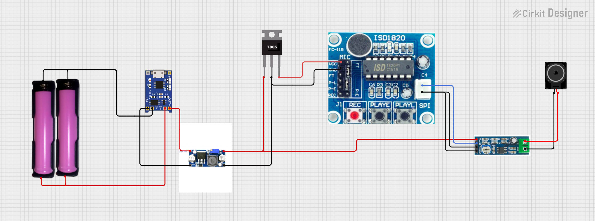
Explore Projects Built with TP4056 + MT3608 Charger Module Step Up
Common Applications
- Charging and powering single-cell lithium-ion or lithium-polymer batteries.
- Boosting battery voltage to power devices like microcontrollers, sensors, or small motors.
- Portable power banks and battery-powered gadgets.
- DIY electronics projects requiring a compact charging and step-up solution.
Technical Specifications
Key Technical Details
| Parameter | Value |
|---|---|
| Input Voltage (Charging) | 4.5V to 5.5V (via micro-USB or IN+ pin) |
| Charging Current | 1A (default, adjustable via resistor) |
| Battery Type Supported | Single-cell lithium-ion/lithium-polymer |
| Output Voltage (Boost) | Adjustable: 2V to 28V |
| Output Current (Boost) | Up to 2A (depends on input and load) |
| Efficiency (Boost) | Up to 93% |
| Dimensions | ~36mm x 17mm x 6mm |
Pin Configuration and Descriptions
TP4056 Charger Section
| Pin Name | Description |
|---|---|
| IN+ | Positive input for charging voltage (4.5V to 5.5V). |
| IN- | Negative input (ground) for charging voltage. |
| BAT+ | Positive terminal for the lithium battery. |
| BAT- | Negative terminal for the lithium battery. |
| OUT+ | Positive output terminal (connected to MT3608 input). |
| OUT- | Negative output terminal (connected to MT3608 input). |
MT3608 Step-Up Converter Section
| Pin Name | Description |
|---|---|
| VIN+ | Positive input voltage (connected to TP4056 OUT+). |
| VIN- | Negative input voltage (connected to TP4056 OUT-). |
| VOUT+ | Positive boosted output voltage (adjustable via potentiometer). |
| VOUT- | Negative boosted output voltage (ground). |
Usage Instructions
How to Use the Module in a Circuit
Connect the Input Voltage for Charging:
- Use a micro-USB cable or connect a 5V DC power source to the
IN+andIN-pins. - Ensure the input voltage is within the range of 4.5V to 5.5V.
- Use a micro-USB cable or connect a 5V DC power source to the
Connect the Lithium Battery:
- Attach the positive terminal of the battery to the
BAT+pin and the negative terminal to theBAT-pin. - The TP4056 will handle the charging process automatically.
- Attach the positive terminal of the battery to the
Adjust the Output Voltage:
- Use the onboard potentiometer to set the desired output voltage from the MT3608 step-up converter.
- Measure the output voltage at the
VOUT+andVOUT-pins using a multimeter while adjusting.
Connect the Load:
- Attach your device or circuit to the
VOUT+andVOUT-pins. - Ensure the load does not exceed the module's maximum output current (2A).
- Attach your device or circuit to the
Important Considerations and Best Practices
- Heat Dissipation: The module may heat up during operation, especially at high currents. Ensure proper ventilation or add a heatsink if necessary.
- Battery Protection: Use a lithium battery with built-in protection circuitry to prevent overcharging, over-discharging, or short circuits.
- Output Voltage Adjustment: Always adjust the output voltage without a load connected to avoid damaging sensitive components.
- Current Limitation: Avoid exceeding the maximum current rating of the module to prevent damage.
Example: Using with Arduino UNO
The module can power an Arduino UNO by boosting the lithium battery voltage to 5V. Below is an example code to blink an LED using the Arduino UNO powered by the module:
// Example code to blink an LED using Arduino UNO powered by TP4056 + MT3608 module

const int ledPin = 13; // Pin connected to the onboard LED

void setup() {
  pinMode(ledPin, OUTPUT); // Set the LED pin as an output
}

void loop() {
  digitalWrite(ledPin, HIGH); // Turn the LED on
  delay(1000);               // Wait for 1 second
  digitalWrite(ledPin, LOW);  // Turn the LED off
  delay(1000);               // Wait for 1 second
}
Troubleshooting and FAQs
Common Issues and Solutions
Module Overheating:
- Cause: Excessive current draw or insufficient ventilation.
- Solution: Reduce the load current or add a heatsink to the module.
Battery Not Charging:
- Cause: Incorrect battery connection or insufficient input voltage.
- Solution: Verify the battery polarity and ensure the input voltage is between 4.5V and 5.5V.
No Output Voltage:
- Cause: Incorrect potentiometer adjustment or disconnected load.
- Solution: Adjust the potentiometer to set the desired output voltage and ensure the load is properly connected.
Output Voltage Fluctuations:
- Cause: Insufficient input power or unstable battery voltage.
- Solution: Use a stable power source and ensure the battery is adequately charged.
FAQs
Q1: Can I use this module to charge multiple batteries in series?
A1: No, the TP4056 is designed for single-cell lithium batteries only. Charging multiple batteries in series may damage the module.
Q2: How do I adjust the charging current?
A2: The charging current can be adjusted by replacing the onboard resistor connected to the TP4056 IC. Refer to the TP4056 datasheet for resistor values corresponding to different charging currents.
Q3: What is the maximum output voltage of the MT3608?
A3: The MT3608 can boost the output voltage up to 28V. However, ensure the load current does not exceed the module's maximum rating.
Q4: Can I use this module with a solar panel?
A4: Yes, as long as the solar panel provides a stable voltage between 4.5V and 5.5V for the TP4056 input.
This concludes the documentation for the TP4056 + MT3608 Charger Module Step Up. For further assistance, refer to the manufacturer's datasheet or contact Shenzhen KWM Electronics Co., Ltd.