How to Use Heart Sensor: Examples, Pinouts, and Specs
Introduction
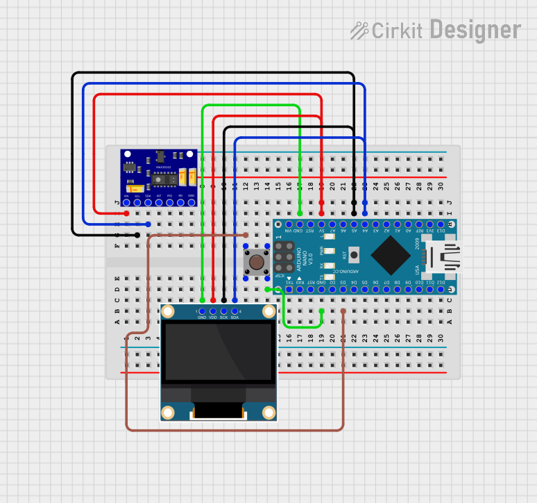
The Heart Sensor (MAXREFDES117), manufactured by Analog Devices, is a compact and highly accurate device designed to monitor and measure heart rate and rhythm. It utilizes optical technology to detect blood flow changes in the body, making it ideal for non-invasive heart rate monitoring. This sensor is widely used in fitness tracking devices, wearable health monitors, and medical applications to assess cardiovascular health.
Explore Projects Built with Heart Sensor
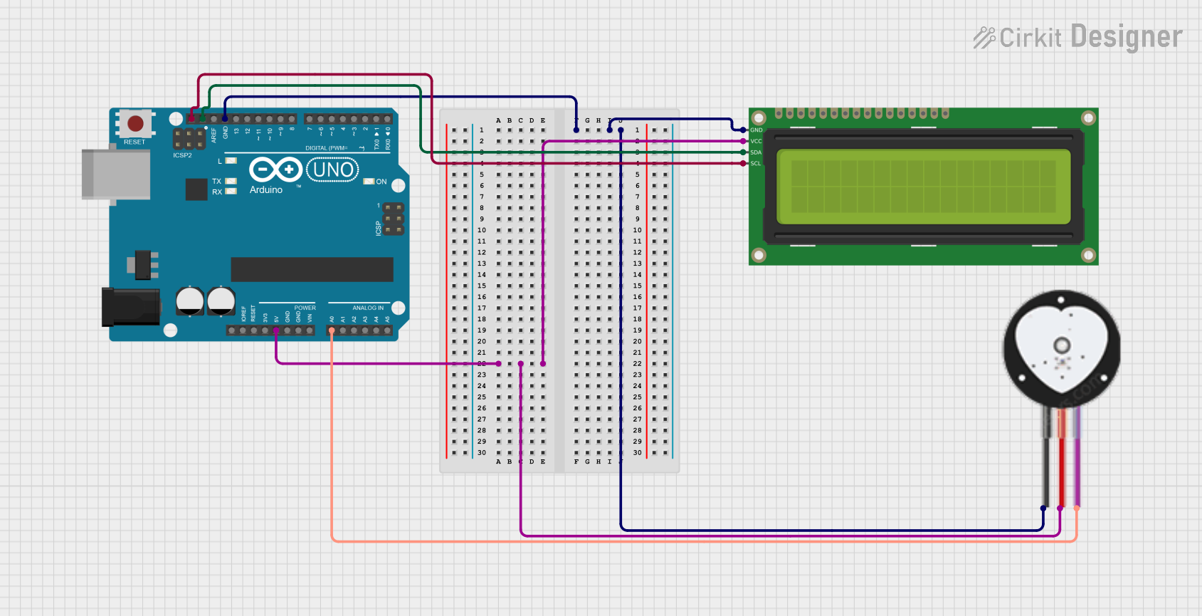
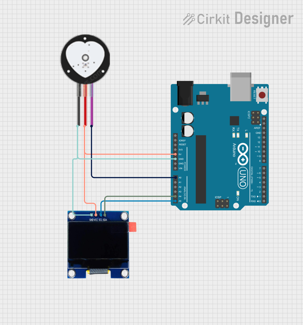
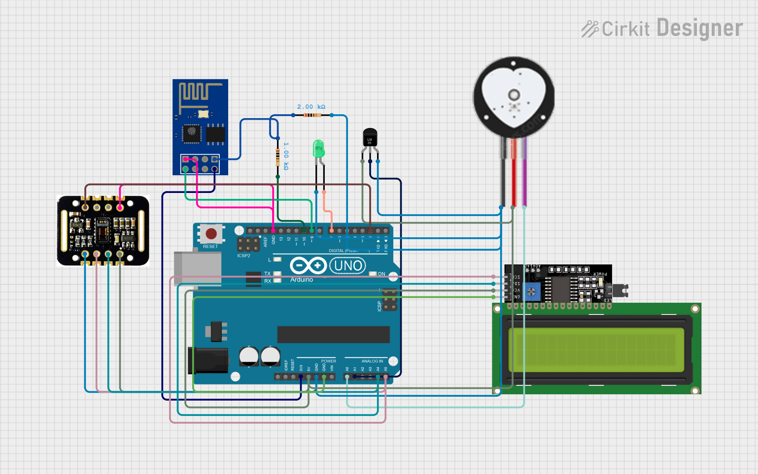
Explore Projects Built with Heart Sensor
Common Applications and Use Cases
- Fitness trackers and smartwatches
- Medical-grade heart rate monitoring devices
- Health and wellness applications
- Research and development in biomedical engineering
- IoT-based health monitoring systems
Technical Specifications
The following table outlines the key technical details of the MAXREFDES117 heart sensor:
| Parameter | Value |
|---|---|
| Manufacturer | Analog Devices |
| Part ID | MAXREFDES117 |
| Operating Voltage | 1.8V to 5.5V |
| Operating Current | 5.5mA (typical) |
| Communication Interface | I2C |
| Sensor Type | Optical (PPG - Photoplethysmography) |
| Wavelengths | Green (537nm), Red (660nm), IR (880nm) |
| Sampling Rate | Configurable (up to 100Hz) |
| Dimensions | 12.7mm x 12.7mm |
| Operating Temperature | -40°C to +85°C |
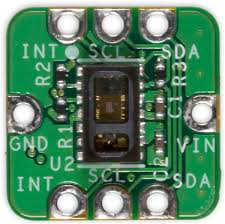
Pin Configuration and Descriptions
The MAXREFDES117 heart sensor has the following pin configuration:
| Pin Name | Pin Number | Description |
|---|---|---|
| VCC | 1 | Power supply input (1.8V to 5.5V) |
| GND | 2 | Ground connection |
| SDA | 3 | I2C data line |
| SCL | 4 | I2C clock line |
| INT | 5 | Interrupt output (optional, active low) |
Usage Instructions
How to Use the Component in a Circuit
- Power Supply: Connect the VCC pin to a regulated power source (1.8V to 5.5V) and the GND pin to the ground.
- I2C Communication: Connect the SDA and SCL pins to the corresponding I2C data and clock lines of your microcontroller. Use pull-up resistors (typically 4.7kΩ) on both lines if not already present.
- Interrupt Pin (Optional): The INT pin can be used to signal events such as new data availability. Connect it to a GPIO pin on your microcontroller if needed.
- Placement: Ensure the sensor is placed in contact with the skin for accurate readings. Avoid excessive movement or poor contact, as this may affect performance.
Important Considerations and Best Practices
- Ambient Light: Minimize exposure to ambient light to reduce noise in the sensor readings.
- Skin Contact: Ensure proper contact with the skin for reliable measurements.
- Sampling Rate: Configure the sampling rate based on your application requirements. Higher rates may consume more power.
- I2C Address: The default I2C address of the MAXREFDES117 is
0x57. Ensure no address conflicts if multiple I2C devices are used.
Example Code for Arduino UNO
Below is an example of how to interface the MAXREFDES117 heart sensor with an Arduino UNO:
#include <Wire.h> // Include the I2C library

#define SENSOR_I2C_ADDRESS 0x57 // Default I2C address of MAXREFDES117

void setup() {
  Wire.begin(); // Initialize I2C communication
  Serial.begin(9600); // Initialize serial communication for debugging

  // Check if the sensor is connected
  Wire.beginTransmission(SENSOR_I2C_ADDRESS);
  if (Wire.endTransmission() == 0) {
    Serial.println("Heart sensor detected!");
  } else {
    Serial.println("Heart sensor not detected. Check connections.");
    while (1); // Halt execution if sensor is not found
  }
}

void loop() {
  // Request data from the sensor
  Wire.beginTransmission(SENSOR_I2C_ADDRESS);
  Wire.write(0x00); // Example register address to read data
  Wire.endTransmission();

  Wire.requestFrom(SENSOR_I2C_ADDRESS, 2); // Request 2 bytes of data
  if (Wire.available() == 2) {
    uint8_t msb = Wire.read(); // Most significant byte
    uint8_t lsb = Wire.read(); // Least significant byte
    int heartRate = (msb << 8) | lsb; // Combine bytes into a single value

    Serial.print("Heart Rate: ");
    Serial.println(heartRate);
  } else {
    Serial.println("Failed to read data from sensor.");
  }

  delay(1000); // Wait 1 second before the next reading
}
Troubleshooting and FAQs
Common Issues and Solutions
Sensor Not Detected
- Cause: Incorrect wiring or I2C address mismatch.
- Solution: Verify the connections and ensure the correct I2C address (
0x57) is used.
Inaccurate Readings
- Cause: Poor skin contact or excessive movement.
- Solution: Ensure the sensor is securely placed against the skin and minimize movement during measurements.
No Data Output
- Cause: Faulty power supply or incorrect register access.
- Solution: Check the power supply voltage and ensure the correct register addresses are used in the code.
Ambient Light Interference
- Cause: High levels of ambient light affecting the sensor.
- Solution: Shield the sensor from direct light sources or use it in a controlled environment.
FAQs
Can the MAXREFDES117 be used with 3.3V microcontrollers?
- Yes, the sensor operates within a voltage range of 1.8V to 5.5V, making it compatible with 3.3V systems.
What is the maximum sampling rate of the sensor?
- The sensor supports a configurable sampling rate of up to 100Hz.
Is the sensor suitable for medical-grade applications?
- While the MAXREFDES117 is highly accurate, its suitability for medical-grade applications depends on the specific certification requirements of your project.
Can the sensor measure SpO2 (blood oxygen levels)?
- Yes, the sensor supports SpO2 measurement when used with appropriate algorithms and processing.
By following this documentation, users can effectively integrate the MAXREFDES117 heart sensor into their projects and troubleshoot common issues.