How to Use selector switch: Examples, Pinouts, and Specs
Introduction
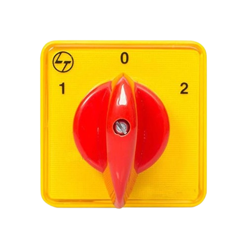
A selector switch, manufactured by SA (Part ID: SA), is an electromechanical device designed to allow users to select between multiple circuit paths or functions. It typically features multiple positions, enabling control over various operations in a circuit. Selector switches are widely used in industrial control panels, machinery, and consumer electronics for their reliability and ease of use.
Explore Projects Built with selector switch
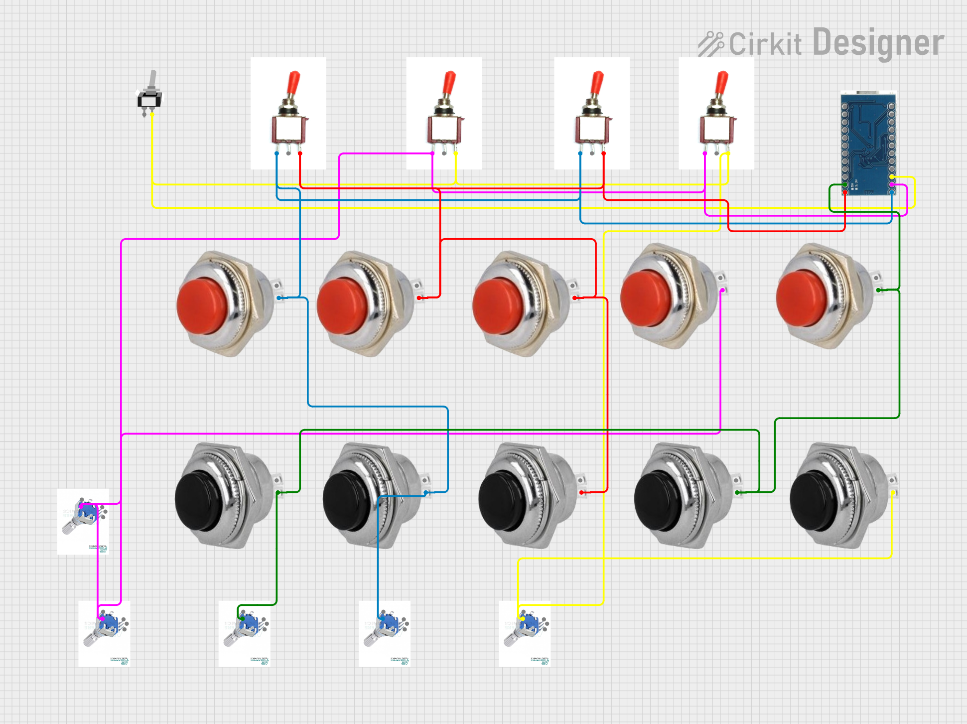

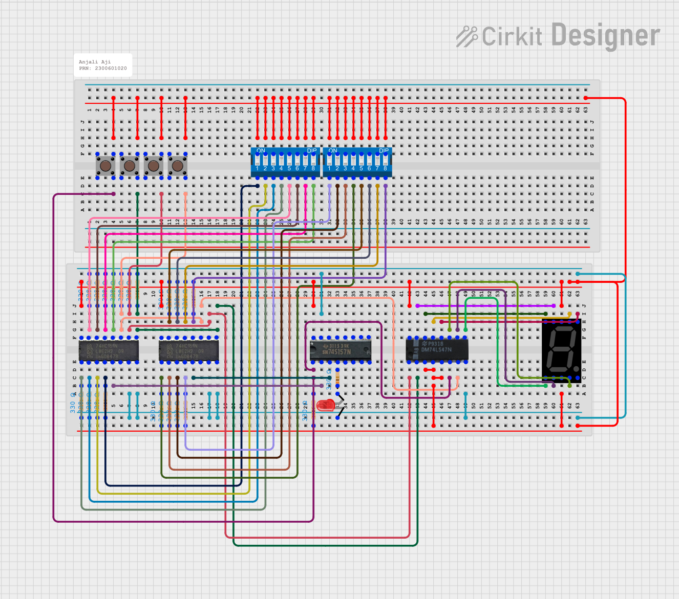

Explore Projects Built with selector switch
Common Applications and Use Cases
- Industrial control systems for selecting machine modes (e.g., manual, automatic, off).
- Consumer electronics for switching between different operational modes.
- Audio equipment for input/output source selection.
- Test and measurement devices for selecting ranges or functions.
- Home automation systems for controlling lighting or appliances.
Technical Specifications
Key Technical Details
- Manufacturer: SA
- Part ID: SA
- Switch Type: Rotary or lever-based selector switch
- Positions: 2 to 12 positions (depending on the model)
- Contact Configuration: Single Pole Single Throw (SPST), Single Pole Double Throw (SPDT), or Double Pole Double Throw (DPDT)
- Voltage Rating: Up to 250V AC/DC (varies by model)
- Current Rating: 5A to 20A (varies by model)
- Mounting Style: Panel mount or PCB mount
- Material: High-durability plastic and metal contacts
- Operating Temperature: -20°C to +70°C
Pin Configuration and Descriptions
The pin configuration of a selector switch depends on its contact configuration. Below is an example for a 3-position SPDT selector switch:
| Pin Number | Description |
|---|---|
| 1 | Common terminal (COM) |
| 2 | Normally Open (NO) terminal for Position 1 |
| 3 | Normally Open (NO) terminal for Position 2 |
For a DPDT selector switch, the pin configuration is as follows:
| Pin Number | Description |
|---|---|
| 1 | Common terminal for Pole 1 (COM1) |
| 2 | Normally Open (NO) terminal for Pole 1, Position 1 |
| 3 | Normally Open (NO) terminal for Pole 1, Position 2 |
| 4 | Common terminal for Pole 2 (COM2) |
| 5 | Normally Open (NO) terminal for Pole 2, Position 1 |
| 6 | Normally Open (NO) terminal for Pole 2, Position 2 |
Usage Instructions
How to Use the Selector Switch in a Circuit
- Determine the Configuration: Identify the number of positions and poles required for your application. For example, a 3-position SPDT switch can toggle between two outputs or functions.
- Connect the Terminals:
- Connect the common terminal (COM) to the input signal or power source.
- Connect the NO terminals to the desired output paths or devices.
- Mount the Switch: Secure the selector switch to a panel or PCB using the appropriate mounting hardware. Ensure the switch is firmly in place to prevent accidental movement.
- Test the Circuit: After wiring, test the circuit to ensure the selector switch operates as intended.
Important Considerations and Best Practices
- Voltage and Current Ratings: Ensure the selector switch's voltage and current ratings match or exceed the requirements of your circuit.
- Debouncing: If the selector switch is used in a digital circuit, consider implementing software or hardware debouncing to avoid false triggering.
- Position Marking: Clearly label the positions of the selector switch to avoid confusion during operation.
- Environmental Conditions: Use selector switches rated for the operating environment, especially in high-temperature or high-humidity conditions.
Example: Connecting a Selector Switch to an Arduino UNO
Below is an example of using a 3-position SPDT selector switch with an Arduino UNO to toggle between three LEDs.
// Define pin connections for the selector switch and LEDs
const int switchPin1 = 2; // NO terminal for Position 1
const int switchPin2 = 3; // NO terminal for Position 2
const int led1 = 8;       // LED for Position 1
const int led2 = 9;       // LED for Position 2
const int led3 = 10;      // LED for Position 3 (default)

// Setup function to initialize pins
void setup() {
  pinMode(switchPin1, INPUT_PULLUP); // Enable internal pull-up resistor
  pinMode(switchPin2, INPUT_PULLUP); // Enable internal pull-up resistor
  pinMode(led1, OUTPUT);
  pinMode(led2, OUTPUT);
  pinMode(led3, OUTPUT);
}

// Main loop to read switch state and control LEDs
void loop() {
  // Read the state of the selector switch
  bool position1 = digitalRead(switchPin1) == LOW; // Active LOW
  bool position2 = digitalRead(switchPin2) == LOW; // Active LOW

  // Control LEDs based on switch position
  if (position1) {
    digitalWrite(led1, HIGH); // Turn on LED1
    digitalWrite(led2, LOW);
    digitalWrite(led3, LOW);
  } else if (position2) {
    digitalWrite(led1, LOW);
    digitalWrite(led2, HIGH); // Turn on LED2
    digitalWrite(led3, LOW);
  } else {
    digitalWrite(led1, LOW);
    digitalWrite(led2, LOW);
    digitalWrite(led3, HIGH); // Default to LED3
  }
}
Troubleshooting and FAQs
Common Issues and Solutions
Switch Not Functioning:
- Cause: Loose or incorrect wiring.
- Solution: Double-check the wiring and ensure all connections are secure.
Intermittent Operation:
- Cause: Contact wear or dirt accumulation.
- Solution: Clean the contacts with a contact cleaner or replace the switch if necessary.
Incorrect Position Detection:
- Cause: Debouncing issues in digital circuits.
- Solution: Implement software debouncing in your microcontroller code.
Overheating:
- Cause: Exceeding the switch's current or voltage rating.
- Solution: Use a switch with appropriate ratings for your application.
FAQs
Q: Can I use a selector switch for AC circuits?
A: Yes, as long as the switch's voltage and current ratings are suitable for the AC circuit.Q: How do I know which position the switch is in?
A: Most selector switches have a physical indicator or detent mechanism to show the current position.Q: Can I use a selector switch with more than two poles?
A: Yes, multi-pole selector switches are available for applications requiring multiple independent circuits.Q: Is the selector switch waterproof?
A: Some models are designed to be waterproof or weather-resistant. Check the product specifications for details.