
How to Use iPod Male Connector: Examples, Pinouts, and Specs
 Design with iPod Male Connector in Cirkit Designer
Introduction
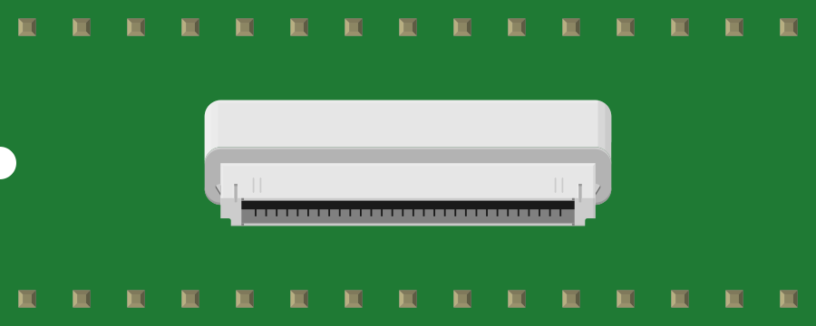
The iPod Male Connector is a proprietary interface designed to connect iPod devices to external systems. This connector supports multiple functionalities, including charging, data transfer, and audio output. It is commonly used in docking stations, audio systems, and custom electronics projects that require integration with iPod devices.
Explore Projects Built with iPod Male Connector
 Open Project in Cirkit Designer
 Open Project in Cirkit Designer
 Open Project in Cirkit Designer
 Open Project in Cirkit Designer
Explore Projects Built with iPod Male Connector
Open Project in Cirkit DesignerOpen Project in Cirkit DesignerOpen Project in Cirkit DesignerOpen Project in Cirkit DesignerCommon Applications and Use Cases
- Charging iPod devices via external power sources
- Transferring data between iPods and computers or other devices
- Audio output for playback through external speakers or headphones
- Integration into custom electronics projects, such as DIY docks or audio amplifiers
Technical Specifications
Key Technical Details
- Connector Type: Proprietary 30-pin male connector
- Voltage Range: 3.3V to 5V (for data and charging lines)
- Current Rating: Up to 1A (charging)
- Supported Protocols: USB 2.0, FireWire (legacy), and analog audio
- Pin Count: 30 pins, each with specific functions for power, data, and audio
Pin Configuration and Descriptions
The iPod Male Connector features 30 pins, each assigned a specific function. Below is a table summarizing the key pin assignments:
| Pin Number | Function | Description |
|---|---|---|
| 1, 2 | GND | Ground connection for power and signal reference |
| 3, 4 | +5V (Power) | Power supply for charging the iPod |
| 7, 8 | Data- (USB) | USB differential data line (negative) |
| 9, 10 | Data+ (USB) | USB differential data line (positive) |
| 11 | FireWire Power | Legacy FireWire power input (12V) |
| 12 | FireWire Ground | Ground for FireWire connection |
| 15, 16 | Audio L | Left audio channel output |
| 17, 18 | Audio R | Right audio channel output |
| 19 | Audio GND | Ground for audio signals |
| 21 | Accessory Detect | Detects connected accessories (e.g., docks, chargers) |
| 23 | Serial TX | Serial communication transmit line |
| 24 | Serial RX | Serial communication receive line |
| 27 | iPod Remote Control | Used for remote control signals |
| 30 | Dock Detect | Detects when the iPod is docked |
Note: Not all pins are used in every application. Some pins are reserved for specific Apple accessories.
Usage Instructions
How to Use the iPod Male Connector in a Circuit
- Identify Required Pins: Determine which pins are necessary for your application (e.g., charging, data transfer, or audio output).
- Soldering: Carefully solder wires to the appropriate pins on the connector. Use a fine-tipped soldering iron and ensure no pins are shorted.
- Power Supply: Provide a stable 5V power source for charging. Ensure the current does not exceed 1A.
- Data Communication: For USB data transfer, connect the Data+ and Data- pins to a USB interface. Use proper shielding to avoid interference.
- Audio Output: Connect the Audio L, Audio R, and Audio GND pins to an amplifier or speaker system for audio playback.
- Accessory Detection: Use the Accessory Detect pin to identify when an accessory is connected. This may require a pull-up resistor.
Important Considerations and Best Practices
- Avoid Overloading: Do not exceed the voltage or current ratings of the connector to prevent damage to the iPod or the connector.
- Pin Protection: Use heat shrink tubing or an enclosure to protect soldered connections from short circuits.
- Compatibility: Ensure the connector is compatible with the specific iPod model you are using, as some older models may have different pin configurations.
- Testing: Verify all connections with a multimeter before connecting the iPod to avoid accidental damage.
Example: Connecting to an Arduino UNO
The iPod Male Connector can be used with an Arduino UNO for serial communication or accessory control. Below is an example of how to detect when an iPod is docked:
// Example code to detect iPod docking using Arduino UNO
const int dockDetectPin = 7; // Pin connected to Dock Detect (Pin 30 on connector)
const int ledPin = 13;       // Built-in LED for status indication

void setup() {
  pinMode(dockDetectPin, INPUT_PULLUP); // Set Dock Detect pin as input with pull-up
  pinMode(ledPin, OUTPUT);             // Set LED pin as output
  Serial.begin(9600);                  // Initialize serial communication
}

void loop() {
  int dockStatus = digitalRead(dockDetectPin); // Read Dock Detect pin state

  if (dockStatus == LOW) { // LOW indicates iPod is docked
    digitalWrite(ledPin, HIGH); // Turn on LED
    Serial.println("iPod is docked.");
  } else {
    digitalWrite(ledPin, LOW);  // Turn off LED
    Serial.println("iPod is not docked.");
  }

  delay(500); // Wait for 500ms before checking again
}
Note: The Dock Detect pin typically requires a pull-up resistor. The Arduino's internal pull-up resistor is enabled in this example.
Troubleshooting and FAQs
Common Issues and Solutions
No Power to iPod
- Cause: Incorrect connection to power pins or insufficient power supply.
- Solution: Verify the +5V and GND connections. Ensure the power supply can provide at least 1A.
No Audio Output
- Cause: Incorrect wiring to audio pins or missing ground connection.
- Solution: Check the connections to Audio L, Audio R, and Audio GND. Ensure proper soldering.
Data Transfer Fails
- Cause: Miswired USB data lines or interference.
- Solution: Verify the Data+ and Data- connections. Use shielded cables for USB lines.
iPod Not Detected
- Cause: Accessory Detect pin not connected or improperly configured.
- Solution: Ensure the Accessory Detect pin is connected and properly pulled up.
FAQs
Can I use this connector with non-iPod devices?
- The connector is designed specifically for iPod devices. While some pins (e.g., USB) may work with other devices, full functionality is not guaranteed.
Is this connector compatible with Lightning devices?
- No, this connector is for older iPod models with the 30-pin interface. Lightning devices require a different connector.
Do I need all 30 pins for basic functionality?
- No, basic functions like charging and audio output only require a subset of the pins.
By following this documentation, you can effectively integrate the iPod Male Connector into your projects while avoiding common pitfalls.