
How to Use ID-12_20: Examples, Pinouts, and Specs
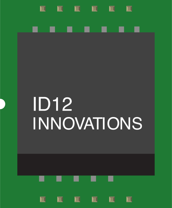
 Design with ID-12_20 in Cirkit Designer
Introduction
The ID-12_20 is a versatile integrated circuit (IC) designed for signal processing and control functions in electronic systems. Known for its reliability and efficiency, this component is widely used in applications requiring precise signal manipulation, such as industrial automation, communication systems, and embedded electronics. Its compact design and robust performance make it a popular choice for engineers and hobbyists alike.
Explore Projects Built with ID-12_20
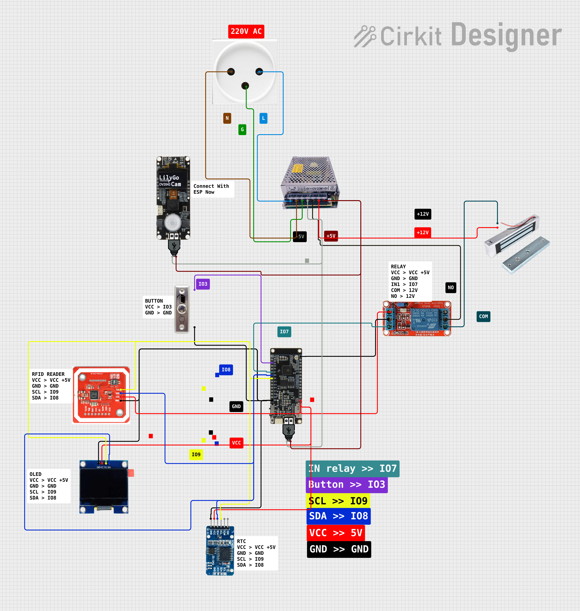 Open Project in Cirkit Designer
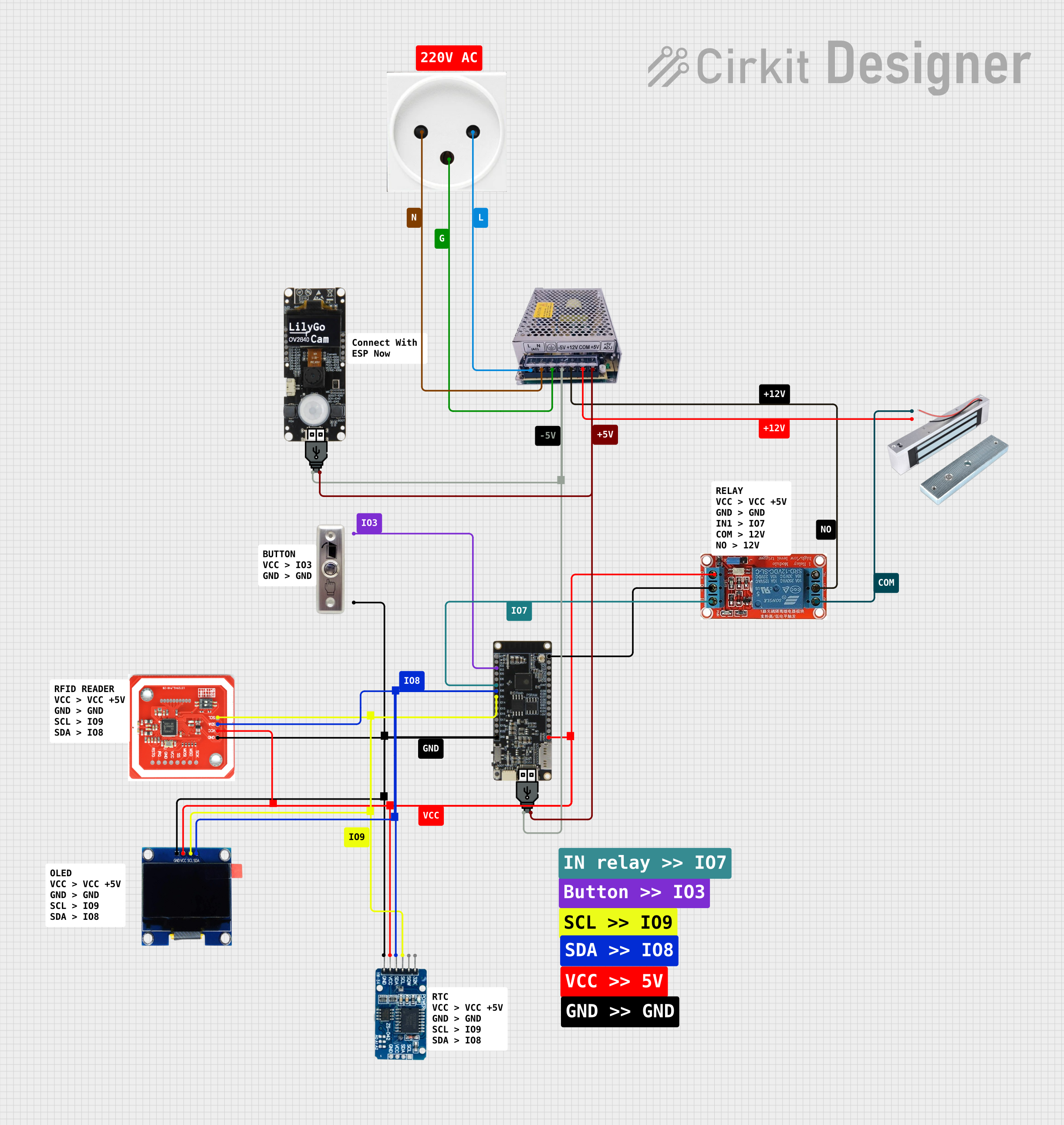 Open Project in Cirkit Designer
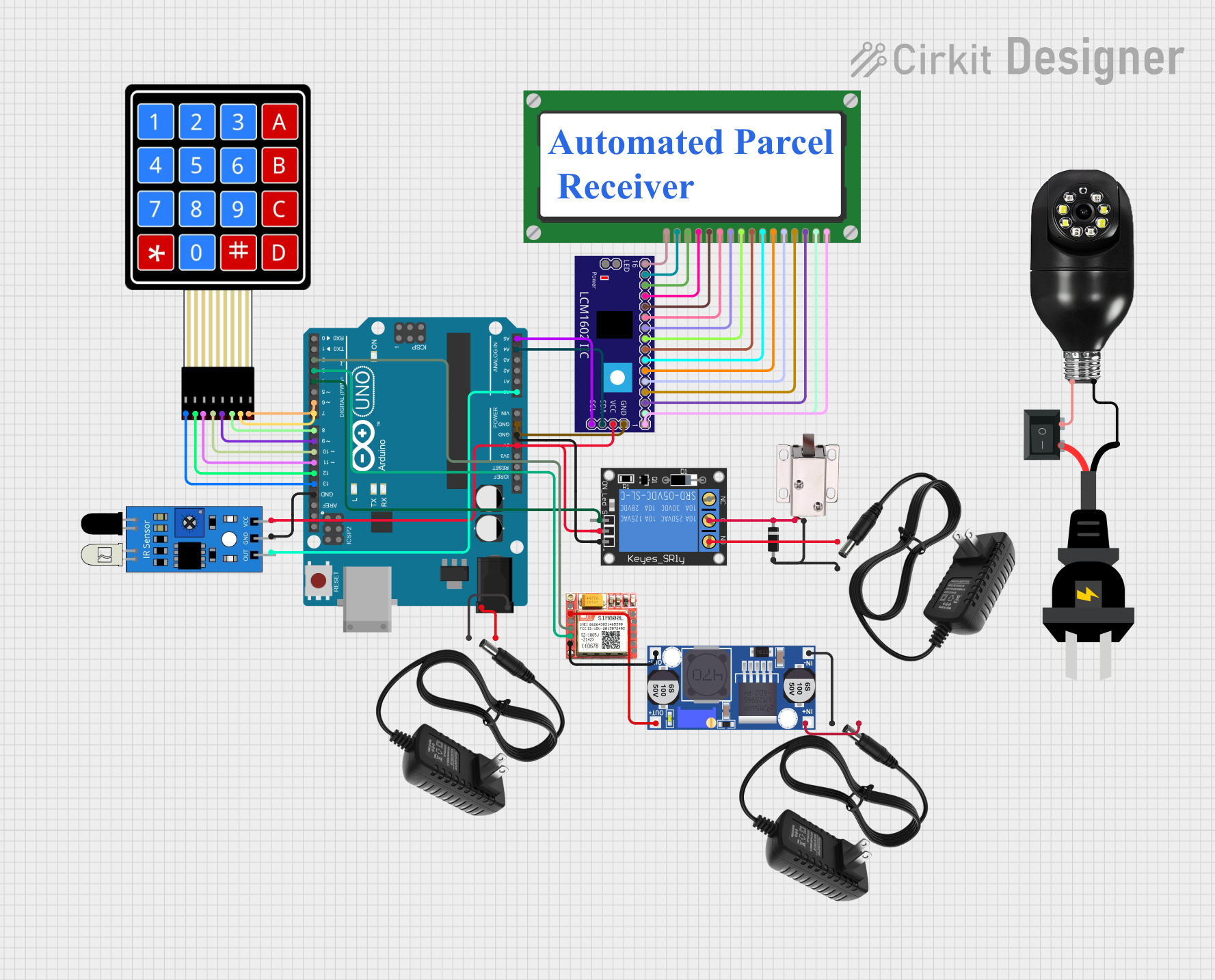 Open Project in Cirkit Designer
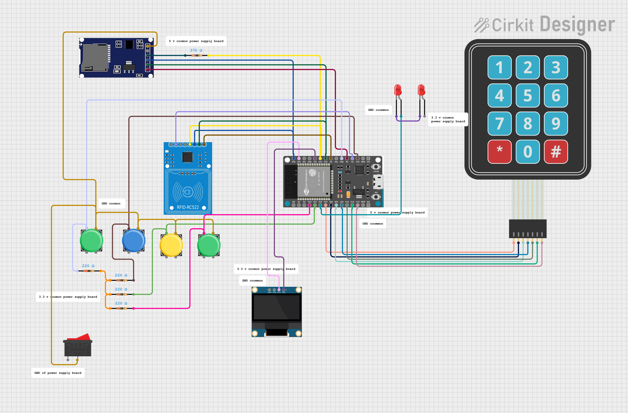 Open Project in Cirkit Designer
Explore Projects Built with ID-12_20
Open Project in Cirkit DesignerOpen Project in Cirkit DesignerOpen Project in Cirkit DesignerOpen Project in Cirkit DesignerCommon Applications:
- Signal processing in communication systems
- Control systems in industrial automation
- Embedded systems for IoT devices
- General-purpose electronic circuits requiring efficient signal handling
Technical Specifications
Key Technical Details:
- Operating Voltage: 3.3V to 5V DC
- Operating Current: 10mA (typical)
- Power Dissipation: 50mW (maximum)
- Operating Temperature Range: -40°C to +85°C
- Package Type: 16-pin Dual In-line Package (DIP)
- Signal Input/Output Levels: TTL-compatible
- Frequency Range: 1kHz to 1MHz (signal processing)
Pin Configuration and Descriptions:
The ID-12_20 features a 16-pin configuration. Below is the pinout and description:
| Pin Number | Pin Name | Description |
|---|---|---|
| 1 | VCC | Power supply input (3.3V to 5V DC) |
| 2 | GND | Ground connection |
| 3 | IN1 | Signal input 1 |
| 4 | IN2 | Signal input 2 |
| 5 | OUT1 | Signal output 1 |
| 6 | OUT2 | Signal output 2 |
| 7 | ENABLE | Enable pin (active HIGH) |
| 8 | RESET | Reset pin (active LOW) |
| 9 | CLK_IN | Clock input for synchronization |
| 10 | CLK_OUT | Clock output for external devices |
| 11 | NC | No connection |
| 12 | NC | No connection |
| 13 | TEST | Test pin (for factory use, leave unconnected in normal operation) |
| 14 | MODE_SEL | Mode selection pin (HIGH for Mode 1, LOW for Mode 2) |
| 15 | OUT3 | Signal output 3 |
| 16 | OUT4 | Signal output 4 |
Usage Instructions
How to Use the ID-12_20 in a Circuit:
- Power Supply: Connect the VCC pin to a stable 3.3V or 5V DC power source and the GND pin to the circuit ground.
- Signal Inputs: Feed the input signals to IN1 and IN2. Ensure the input levels are TTL-compatible.
- Signal Outputs: Connect the desired output pins (OUT1, OUT2, OUT3, OUT4) to the corresponding circuit components.
- Enable Functionality: Use the ENABLE pin to activate the IC. Set it HIGH to enable the component.
- Reset Functionality: To reset the IC, momentarily pull the RESET pin LOW.
- Clock Synchronization: If required, provide an external clock signal to CLK_IN or use CLK_OUT to synchronize other devices.
- Mode Selection: Use the MODE_SEL pin to configure the IC's operating mode. Set it HIGH for Mode 1 or LOW for Mode 2.
Important Considerations:
- Always decouple the power supply with a 0.1µF capacitor close to the VCC pin to reduce noise.
- Avoid leaving unused input pins floating; connect them to GND or VCC as appropriate.
- Do not exceed the maximum voltage or current ratings to prevent damage to the IC.
- For optimal performance, ensure the input signal frequency is within the specified range (1kHz to 1MHz).
Example: Using ID-12_20 with Arduino UNO
The ID-12_20 can be interfaced with an Arduino UNO for signal processing tasks. Below is an example code snippet:
// Example: Interfacing ID-12_20 with Arduino UNO
// This code demonstrates enabling the IC and reading outputs

#define ENABLE_PIN 7  // Arduino pin connected to ID-12_20 ENABLE pin
#define RESET_PIN 8   // Arduino pin connected to ID-12_20 RESET pin
#define OUT1_PIN 2    // Arduino pin connected to ID-12_20 OUT1 pin
#define OUT2_PIN 3    // Arduino pin connected to ID-12_20 OUT2 pin

void setup() {
  pinMode(ENABLE_PIN, OUTPUT); // Set ENABLE pin as output
  pinMode(RESET_PIN, OUTPUT);  // Set RESET pin as output
  pinMode(OUT1_PIN, INPUT);    // Set OUT1 pin as input
  pinMode(OUT2_PIN, INPUT);    // Set OUT2 pin as input

  digitalWrite(RESET_PIN, HIGH); // Ensure IC is not in reset state
  digitalWrite(ENABLE_PIN, HIGH); // Enable the IC
}

void loop() {
  int output1 = digitalRead(OUT1_PIN); // Read signal from OUT1
  int output2 = digitalRead(OUT2_PIN); // Read signal from OUT2

  // Print the output values to the Serial Monitor
  Serial.begin(9600);
  Serial.print("OUT1: ");
  Serial.println(output1);
  Serial.print("OUT2: ");
  Serial.println(output2);

  delay(1000); // Wait for 1 second before reading again
}
Troubleshooting and FAQs
Common Issues:
No Output Signal:
- Ensure the ENABLE pin is set HIGH.
- Verify that the input signals are within the specified frequency range.
- Check the power supply connections and ensure proper voltage levels.
Erratic Behavior:
- Add a decoupling capacitor (0.1µF) near the VCC pin to reduce noise.
- Verify that unused input pins are not left floating.
Overheating:
- Ensure the IC is not operating beyond its maximum power dissipation (50mW).
- Check for short circuits or incorrect connections.
Clock Synchronization Issues:
- Verify the external clock signal is stable and within the supported frequency range.
- Ensure proper connections to the CLK_IN and CLK_OUT pins.
FAQs:
Q: Can the ID-12_20 operate at 3.3V?
A: Yes, the IC supports an operating voltage range of 3.3V to 5V.Q: What happens if the RESET pin is left floating?
A: The IC may behave unpredictably. Always pull the RESET pin HIGH during normal operation.Q: Can I use the NC pins for additional connections?
A: No, the NC (No Connection) pins should remain unconnected as they are not internally connected.Q: How do I select between Mode 1 and Mode 2?
A: Use the MODE_SEL pin. Set it HIGH for Mode 1 or LOW for Mode 2.
By following this documentation, users can effectively integrate the ID-12_20 into their electronic projects and troubleshoot common issues with ease.