
How to Use at8952: Examples, Pinouts, and Specs
 Design with at8952 in Cirkit Designer
Introduction
The AT8952 is an 8-bit microcontroller from the Atmel AVR family, designed for use in embedded systems. It features 8 KB of flash memory, 512 bytes of SRAM, and a robust architecture suitable for a wide range of applications. The AT8952 is commonly used in projects requiring device control, data processing, and communication with peripheral devices. Its compact design and versatile functionality make it a popular choice for hobbyists and professionals alike.
Explore Projects Built with at8952
 Open Project in Cirkit Designer
 Open Project in Cirkit Designer
 Open Project in Cirkit Designer
 Open Project in Cirkit Designer
Explore Projects Built with at8952
Open Project in Cirkit DesignerOpen Project in Cirkit DesignerOpen Project in Cirkit DesignerOpen Project in Cirkit DesignerCommon Applications
- Home automation systems
- Industrial control systems
- Data acquisition and processing
- Robotics and motor control
- IoT (Internet of Things) devices
Technical Specifications
The AT8952 microcontroller is equipped with the following key features:
| Specification | Details |
|---|---|
| Architecture | 8-bit |
| Flash Memory | 8 KB |
| SRAM | 512 bytes |
| EEPROM | 256 bytes |
| Operating Voltage | 4.0V to 5.5V |
| Clock Speed | Up to 12 MHz |
| I/O Pins | 32 (4 ports: P0, P1, P2, P3) |
| Timers | 2 (16-bit Timer/Counter) |
| Communication Interfaces | UART, SPI, I2C |
| Interrupts | 6 external interrupts |
| Power Consumption | Low power in idle and power-down modes |
Pin Configuration
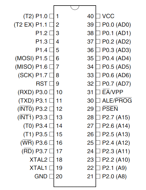
The AT8952 has a 40-pin Dual Inline Package (DIP) layout. Below is the pin configuration:
| Pin Number | Pin Name | Description |
|---|---|---|
| 1-8 | P1.0-P1.7 | Port 1: General-purpose I/O pins |
| 9 | RST | Reset input (active high) |
| 10-17 | P3.0-P3.7 | Port 3: I/O pins with alternate functions |
| 18-19 | XTAL1, XTAL2 | Crystal oscillator pins |
| 20 | GND | Ground |
| 21-28 | P2.0-P2.7 | Port 2: General-purpose I/O pins |
| 29 | PSEN | Program Store Enable |
| 30 | ALE | Address Latch Enable |
| 31 | EA | External Access Enable |
| 32-39 | P0.0-P0.7 | Port 0: General-purpose I/O pins |
| 40 | VCC | Power supply |
Usage Instructions
Using the AT8952 in a Circuit
- Power Supply: Connect the VCC pin to a 5V power source and the GND pin to ground.
- Clock Configuration: Attach a crystal oscillator (e.g., 12 MHz) to the XTAL1 and XTAL2 pins, along with two 22 pF capacitors to stabilize the clock signal.
- Reset Circuit: Connect the RST pin to a pull-up resistor (e.g., 10 kΩ) and a push-button to ground for manual reset functionality.
- I/O Pins: Use the ports (P0, P1, P2, P3) for interfacing with external devices such as LEDs, sensors, or motors.
- Programming: Use an external programmer to load your code into the microcontroller's flash memory via the programming interface.
Important Considerations
- Ensure the operating voltage is within the specified range (4.0V to 5.5V) to avoid damage.
- Use decoupling capacitors (e.g., 0.1 µF) near the power pins to reduce noise and stabilize the power supply.
- Configure unused pins as inputs with pull-up resistors or outputs to prevent floating states.
Example: Blinking an LED with AT8952 and Arduino UNO
The AT8952 can be programmed using an Arduino UNO as an ISP (In-System Programmer). Below is an example code to blink an LED connected to P1.0:
// AT8952 LED Blink Example
// This code blinks an LED connected to P1.0 of the AT8952 microcontroller.
// Ensure the AT8952 is connected to the Arduino UNO as an ISP programmer.

#include <avr/io.h>
#include <util/delay.h>

#define LED_PIN 0 // Define LED pin as P1.0

int main(void) {
    // Configure P1.0 as output
    P1 = 0x00; // Clear Port 1
    P1 |= (1 << LED_PIN); // Set P1.0 as output

    while (1) {
        P1 ^= (1 << LED_PIN); // Toggle P1.0
        _delay_ms(500); // Delay for 500 ms
    }

    return 0;
}
Steps to Upload Code:
- Connect the AT8952 to the Arduino UNO using the ISP pins.
- Load the ArduinoISP sketch onto the Arduino UNO.
- Use the AVRDUDE tool or a compatible IDE to upload the compiled code to the AT8952.
Troubleshooting and FAQs
Common Issues
Microcontroller Not Responding:
- Check the power supply connections and ensure the voltage is within the specified range.
- Verify the crystal oscillator and capacitors are correctly connected.
Code Upload Fails:
- Ensure the Arduino UNO is correctly configured as an ISP programmer.
- Check the connections between the Arduino and the AT8952.
I/O Pins Not Working:
- Confirm the pins are configured correctly as inputs or outputs in the code.
- Check for short circuits or incorrect wiring.
FAQs
Q: Can I use a different clock frequency?
A: Yes, the AT8952 supports clock frequencies up to 12 MHz. Ensure the crystal oscillator and capacitors are compatible with the chosen frequency.
Q: How do I protect the microcontroller from voltage spikes?
A: Use a voltage regulator and decoupling capacitors to stabilize the power supply and protect against voltage fluctuations.
Q: Can I use the AT8952 for low-power applications?
A: Yes, the AT8952 supports idle and power-down modes to reduce power consumption.
By following this documentation, you can effectively integrate the AT8952 microcontroller into your projects and troubleshoot common issues.