
How to Use SWITCH-DPDT: Examples, Pinouts, and Specs
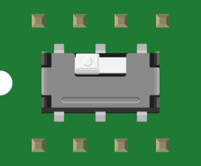
 Design with SWITCH-DPDT in Cirkit Designer
Introduction
A Double Pole Double Throw (DPDT) switch is an electrical switch designed to control two separate circuits simultaneously. It features two input terminals and four output terminals, allowing each input to connect to one of two outputs. This configuration enables versatile control, such as reversing motor direction, switching between power sources, or toggling between two different devices.
Explore Projects Built with SWITCH-DPDT
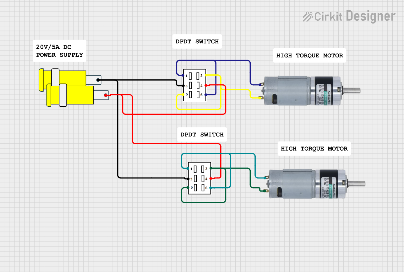 Open Project in Cirkit Designer
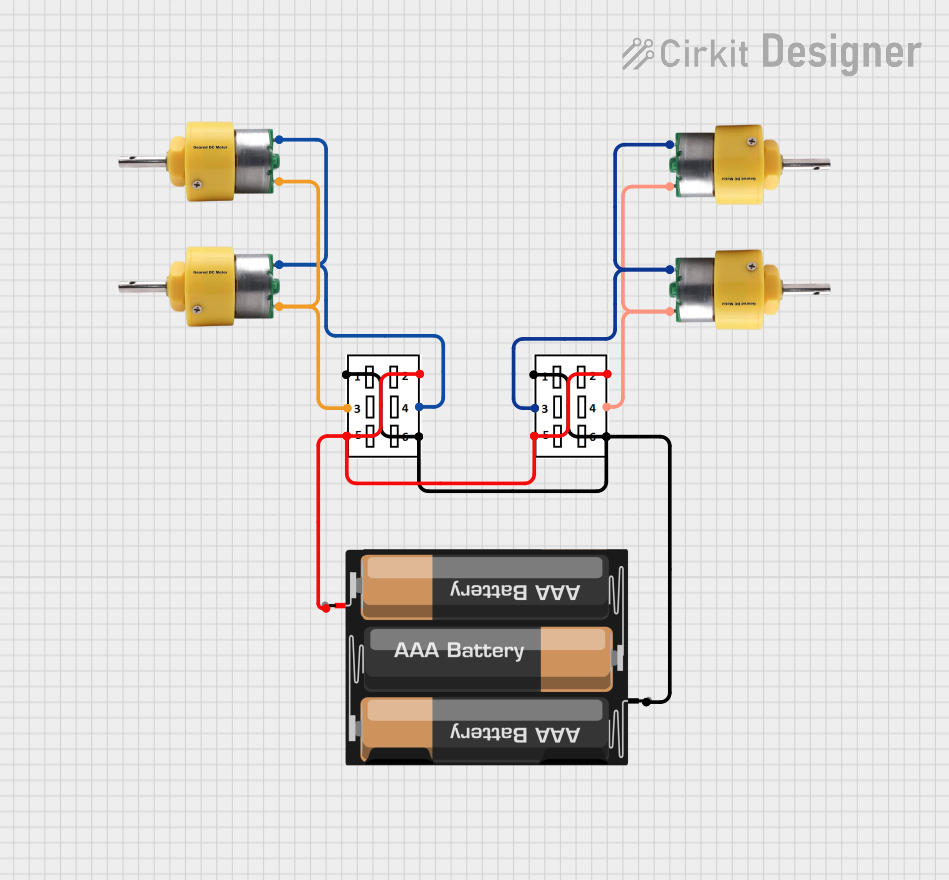 Open Project in Cirkit Designer
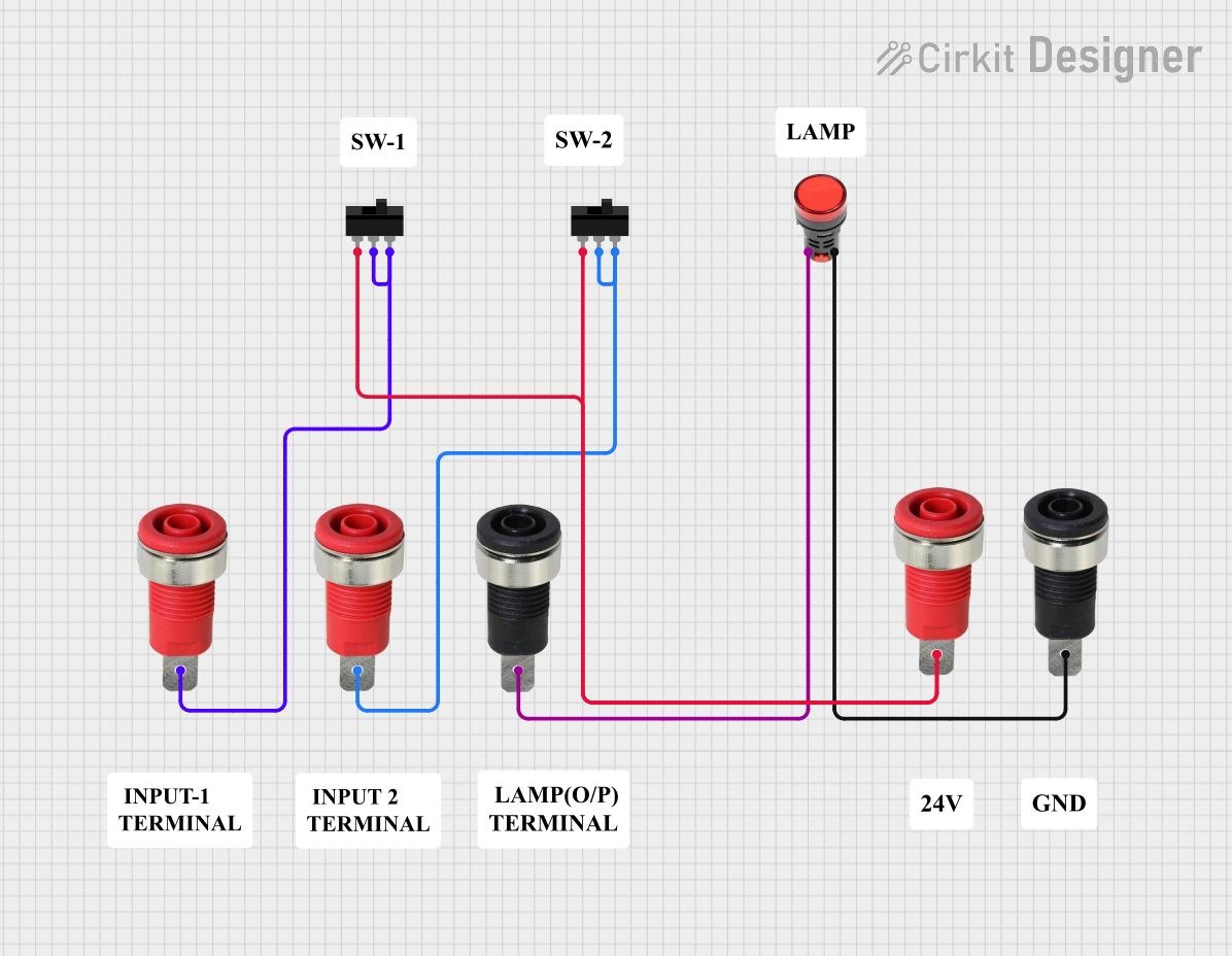 Open Project in Cirkit Designer
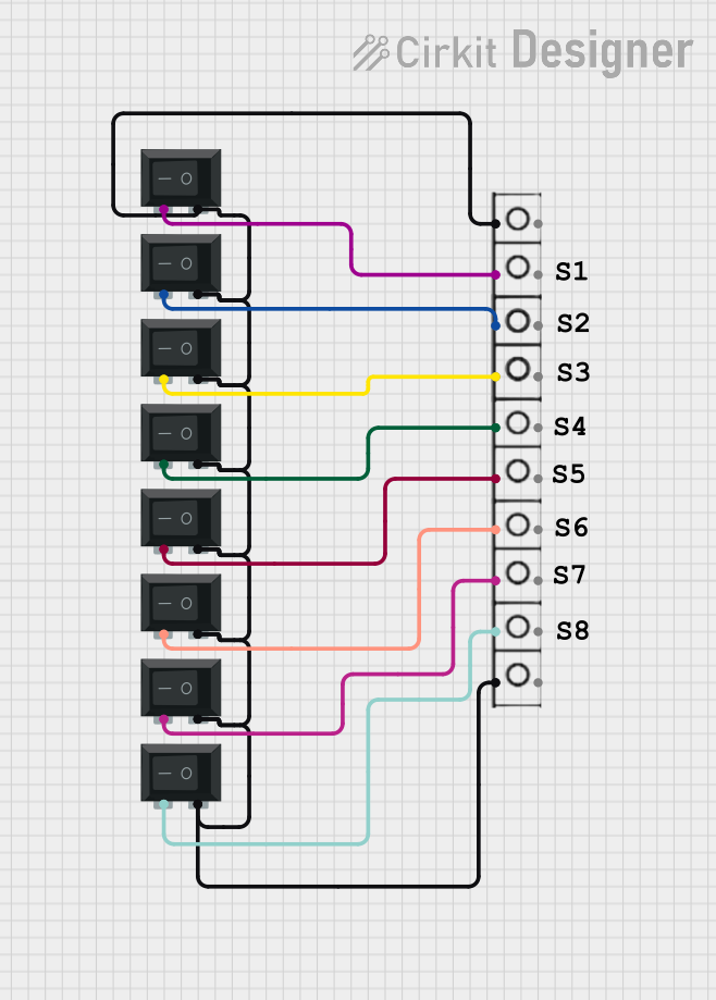 Open Project in Cirkit Designer
Explore Projects Built with SWITCH-DPDT
Open Project in Cirkit DesignerOpen Project in Cirkit DesignerOpen Project in Cirkit DesignerOpen Project in Cirkit DesignerCommon Applications and Use Cases
- Reversing the polarity of DC motors (e.g., for robotics or automation systems)
- Switching between two power sources (e.g., battery and mains power)
- Audio signal routing (e.g., selecting between two audio inputs)
- Controlling two independent circuits with a single switch
Technical Specifications
Key Technical Details
- Switch Type: Double Pole Double Throw (DPDT)
- Number of Poles: 2
- Number of Throws: 2
- Voltage Rating: Typically 12V to 250V (varies by model)
- Current Rating: Typically 2A to 15A (varies by model)
- Contact Configuration: 6 terminals (2 inputs, 4 outputs)
- Switching Mechanism: Toggle, slide, or rocker (depending on the model)
- Mounting Style: Panel mount or PCB mount
Pin Configuration and Descriptions
The DPDT switch has six terminals, as shown in the table below:
| Pin Number | Description |
|---|---|
| 1 | Input 1 (Pole 1) |
| 2 | Output 1A (Throw 1 for Pole 1) |
| 3 | Output 1B (Throw 2 for Pole 1) |
| 4 | Input 2 (Pole 2) |
| 5 | Output 2A (Throw 1 for Pole 2) |
| 6 | Output 2B (Throw 2 for Pole 2) |
Note: The exact pin numbering may vary depending on the manufacturer. Always refer to the datasheet for your specific DPDT switch.
Usage Instructions
How to Use the Component in a Circuit
- Identify the Terminals: Locate the two input terminals (Pins 1 and 4) and the four output terminals (Pins 2, 3, 5, and 6).
- Connect the Inputs: Attach the two circuits or power sources to the input terminals (Pins 1 and 4).
- Connect the Outputs: Connect the devices or loads to the output terminals (Pins 2, 3, 5, and 6).
- Switch Operation: Toggle the switch to change the connection between the inputs and outputs:
- In one position, Input 1 connects to Output 1A, and Input 2 connects to Output 2A.
- In the other position, Input 1 connects to Output 1B, and Input 2 connects to Output 2B.
Important Considerations and Best Practices
- Voltage and Current Ratings: Ensure the switch's voltage and current ratings are suitable for your application to avoid damage or failure.
- Debouncing: Mechanical switches may produce noise or "bouncing" when toggled. Use a debouncing circuit or software to ensure stable operation in digital systems.
- Mounting: Securely mount the switch to prevent accidental disconnections or damage.
- Polarity: When reversing polarity (e.g., for motors), double-check connections to avoid short circuits.
Example: Reversing a DC Motor with Arduino UNO
A DPDT switch can be used to reverse the direction of a DC motor. Below is an example circuit and Arduino code to control the motor using the switch.
Circuit Description
- Connect the motor terminals to the DPDT switch outputs (Pins 2, 3 for one direction and Pins 5, 6 for the reverse direction).
- Connect the switch inputs (Pins 1 and 4) to the motor power supply.
- Use the Arduino to monitor the switch state and control the motor.
Arduino Code
// Define the input pins for the DPDT switch
const int switchPin1 = 2; // Pin connected to DPDT switch input 1
const int switchPin2 = 3; // Pin connected to DPDT switch input 2

// Define the output pins for the motor
const int motorPin1 = 9;  // Motor control pin 1
const int motorPin2 = 10; // Motor control pin 2

void setup() {
  // Set switch pins as inputs
  pinMode(switchPin1, INPUT);
  pinMode(switchPin2, INPUT);

  // Set motor pins as outputs
  pinMode(motorPin1, OUTPUT);
  pinMode(motorPin2, OUTPUT);

  // Initialize motor pins to LOW
  digitalWrite(motorPin1, LOW);
  digitalWrite(motorPin2, LOW);
}

void loop() {
  // Read the state of the DPDT switch
  int switchState1 = digitalRead(switchPin1);
  int switchState2 = digitalRead(switchPin2);

  // Control the motor direction based on the switch state
  if (switchState1 == HIGH && switchState2 == LOW) {
    // Forward direction
    digitalWrite(motorPin1, HIGH);
    digitalWrite(motorPin2, LOW);
  } else if (switchState1 == LOW && switchState2 == HIGH) {
    // Reverse direction
    digitalWrite(motorPin1, LOW);
    digitalWrite(motorPin2, HIGH);
  } else {
    // Stop the motor
    digitalWrite(motorPin1, LOW);
    digitalWrite(motorPin2, LOW);
  }
}
Troubleshooting and FAQs
Common Issues and Solutions
Switch Doesn't Work:
- Cause: Incorrect wiring or loose connections.
- Solution: Double-check the wiring and ensure all connections are secure.
Motor Doesn't Reverse:
- Cause: Incorrect pin connections or faulty switch.
- Solution: Verify the pin configuration and test the switch with a multimeter.
Switch Overheats:
- Cause: Exceeding the voltage or current rating.
- Solution: Use a switch with appropriate ratings for your application.
Noise or Bouncing:
- Cause: Mechanical switch contacts.
- Solution: Add a debouncing circuit or use software debouncing.
FAQs
Q: Can I use a DPDT switch for AC circuits?
- A: Yes, as long as the switch's voltage and current ratings are suitable for the AC application.
Q: How do I identify the terminals on my DPDT switch?
- A: Refer to the datasheet or use a multimeter to test continuity between terminals in different switch positions.
Q: Can I use a DPDT switch to control LEDs?
- A: Yes, but ensure the LEDs are connected with appropriate resistors to limit current.
This concludes the documentation for the SWITCH-DPDT.