How to Use 1 Channel Way Optocoupler Isolation Module PC817 EL817 12V: Examples, Pinouts, and Specs
Introduction
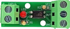
The 1 Channel Way Optocoupler Isolation Module (Manufacturer: AC, Part ID: Optocoupler) is a compact and reliable module designed to provide electrical isolation between input and output circuits. It uses the PC817 or EL817 optocoupler IC, which is widely recognized for its efficiency and stability. This module operates at 12V, making it ideal for applications requiring signal transfer while protecting sensitive components from high voltage surges.
Explore Projects Built with 1 Channel Way Optocoupler Isolation Module PC817 EL817 12V


Explore Projects Built with 1 Channel Way Optocoupler Isolation Module PC817 EL817 12V
Common Applications and Use Cases
- Electrical isolation in microcontroller-based circuits
- Signal level shifting between high and low voltage systems
- Noise suppression in industrial control systems
- Protection of sensitive components in power electronics
- Interfacing between high-voltage devices and low-voltage logic circuits
Technical Specifications
Below are the key technical details and pin configurations for the module:
Key Technical Details
| Parameter | Value |
|---|---|
| Operating Voltage | 12V DC |
| Optocoupler IC | PC817 or EL817 |
| Input Current | 5-20 mA |
| Output Voltage Range | 0-30V DC |
| Isolation Voltage | 5 kV (typical) |
| Response Time | 2-4 µs |
| Operating Temperature | -30°C to +85°C |
| Dimensions | 25mm x 15mm x 10mm (approx.) |
Pin Configuration and Descriptions
| Pin Number | Pin Name | Description |
|---|---|---|
| 1 | VCC (Input) | Positive input voltage (12V DC) for the optocoupler module. |
| 2 | GND (Input) | Ground connection for the input side. |
| 3 | Signal (Input) | Signal input pin to drive the optocoupler (logic HIGH or LOW). |
| 4 | VOUT (Output) | Output voltage pin, isolated from the input side. |
| 5 | GND (Output) | Ground connection for the output side, isolated from the input ground. |
Usage Instructions
How to Use the Component in a Circuit
- Power the Module: Connect the input side of the module to a 12V DC power supply. Ensure proper polarity by connecting VCC to the positive terminal and GND to the negative terminal.
- Input Signal: Feed the signal to the
Signal (Input)pin. This signal can be a logic HIGH (e.g., 5V) or LOW (e.g., 0V) from a microcontroller or other control circuit. - Output Signal: The optocoupler will transfer the input signal to the output side while maintaining electrical isolation. The output signal can be read from the
VOUTpin, with theGND (Output)pin serving as the reference ground.
Important Considerations and Best Practices
- Input Current Limiting: Use a current-limiting resistor on the input signal line to prevent excessive current through the optocoupler's LED. For a 12V input, a 1kΩ resistor is typically sufficient.
- Output Pull-Up Resistor: If the output is connected to a digital input pin of a microcontroller, use a pull-up resistor (e.g., 10kΩ) to ensure a stable HIGH signal when the optocoupler is off.
- Isolation: Ensure that the input and output grounds are not connected to maintain proper isolation.
- Voltage Compatibility: Verify that the output voltage range of the module matches the requirements of the connected circuit.
Example: Connecting to an Arduino UNO
Below is an example of how to connect the module to an Arduino UNO to read an isolated input signal:
Circuit Connections
- Connect the module's
VCC (Input)andGND (Input)to the Arduino's 5V and GND pins, respectively. - Connect the
Signal (Input)pin to a digital output pin on the Arduino (e.g., pin 7). - Connect the
VOUT (Output)pin to a digital input pin on the Arduino (e.g., pin 2). - Connect the
GND (Output)pin to the Arduino's GND.
Arduino Code
// Define pin connections
const int signalPin = 7;  // Pin connected to the module's Signal (Input)
const int outputPin = 2;  // Pin connected to the module's VOUT (Output)

void setup() {
  pinMode(signalPin, OUTPUT);  // Set signal pin as output
  pinMode(outputPin, INPUT);   // Set output pin as input
  Serial.begin(9600);          // Initialize serial communication
}

void loop() {
  // Send a HIGH signal to the optocoupler input
  digitalWrite(signalPin, HIGH);
  delay(1000);  // Wait for 1 second

  // Read the isolated output signal
  int outputState = digitalRead(outputPin);
  Serial.print("Output State: ");
  Serial.println(outputState);

  // Send a LOW signal to the optocoupler input
  digitalWrite(signalPin, LOW);
  delay(1000);  // Wait for 1 second
}
Troubleshooting and FAQs
Common Issues and Solutions
No Output Signal:
- Ensure the input signal is within the specified voltage range (5-12V).
- Check the current-limiting resistor on the input side; it may be too high or missing.
- Verify that the output side is properly connected, including any required pull-up resistor.
Output Signal is Unstable:
- Add a pull-up resistor to the output pin if not already present.
- Check for noise or interference on the input signal line.
No Isolation Between Input and Output:
- Ensure that the input and output grounds are not connected.
- Verify the integrity of the optocoupler IC (PC817/EL817) and replace it if necessary.
Module Overheating:
- Check the input current and ensure it does not exceed the module's specifications.
- Verify that the module is not exposed to temperatures beyond its operating range.
FAQs
Q: Can this module be used with a 3.3V microcontroller?
A: Yes, but you may need to adjust the current-limiting resistor on the input side to ensure proper operation with a 3.3V signal.
Q: What is the maximum frequency this module can handle?
A: The module can handle signals with frequencies up to approximately 100 kHz, depending on the specific optocoupler IC used.
Q: Is the module suitable for AC signal isolation?
A: No, this module is designed for DC signal isolation only. For AC signals, consider using a specialized optocoupler module.
Q: Can I use this module for bidirectional communication?
A: No, this module is designed for unidirectional signal transfer. For bidirectional communication, use a different type of isolation module.