How to Use LDR Module 3 pin: Examples, Pinouts, and Specs
Introduction
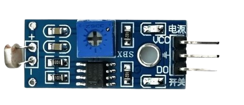
The Charan Light Dependent Resistor (LDR) Module is an electronic sensor that detects the intensity of light. As the ambient light level changes, the resistance across the LDR varies. This module is commonly used in applications such as light detection, automatic brightness control, and security systems. It is designed with three pins for easy integration into various circuits and projects.
Explore Projects Built with LDR Module 3 pin
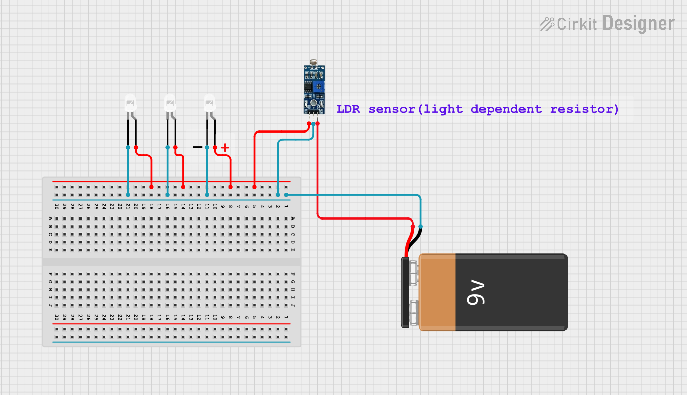

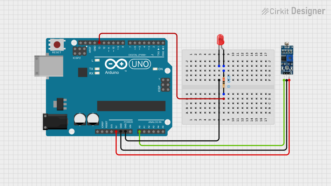
Explore Projects Built with LDR Module 3 pin
Technical Specifications
Key Technical Details
- Operating Voltage: 3.3V to 5V
- Output Type: Analog voltage corresponding to light intensity
- Max Power Dissipation: Typically around 100 mW
- Light Resistance (10 Lux): 50-100 kΩ
- Dark Resistance: Over 1 MΩ
- Response Time: 20-30 ms
- Peak Spectral Response: 540 nm
- Operating Temperature: -30°C to +70°C
Pin Configuration and Descriptions
| Pin Number | Name | Description |
|---|---|---|
| 1 | VCC | Connect to 3.3V or 5V power supply |
| 2 | OUT | Analog output voltage |
| 3 | GND | Ground connection |
Usage Instructions
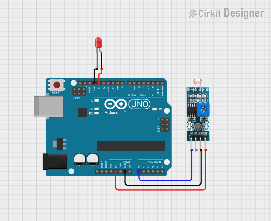
Integration into a Circuit
- Power Connection: Connect the VCC pin to a 3.3V or 5V power supply.
- Ground Connection: Connect the GND pin to the ground of the power supply.
- Signal Output: Connect the OUT pin to an analog input on a microcontroller to read the light levels.
Important Considerations and Best Practices
- Ensure that the operating voltage does not exceed the module's maximum rating to prevent damage.
- Avoid placing the LDR in direct sunlight or high-intensity light without proper calibration, as this may saturate the sensor.
- Use a pull-down resistor if necessary to ensure a stable output when the light level is low.
- Calibrate the sensor in the specific environment where it will be used to get accurate readings.
Example Code for Arduino UNO
// Define the LDR module's output pin
const int ldrPin = A0;

void setup() {
  // Initialize serial communication at 9600 bits per second:
  Serial.begin(9600);
}

void loop() {
  // Read the input on analog pin 0:
  int sensorValue = analogRead(ldrPin);
  // Convert the analog reading (which goes from 0 - 1023) to a voltage (0 - 5V):
  float voltage = sensorValue * (5.0 / 1023.0);
  // Print out the value you read:
  Serial.println(voltage);
  delay(1000); // Delay a second between readings
}
Troubleshooting and FAQs
Common Issues
- Inconsistent Readings: Ensure that there are no loose connections and that the LDR is not exposed to intermittent light sources.
- No Output: Verify that the VCC and GND pins are correctly connected and that the power supply is within the specified voltage range.
- Saturated Sensor: If the sensor is in a very bright environment, it may become saturated. Use a shade or adjust the angle of exposure.
Solutions and Tips for Troubleshooting
- Calibration: Use a known light source to calibrate the sensor for more accurate readings.
- Shielding: Shield the LDR from other light sources if you're only interested in one particular light source.
- Serial Output: Use the serial output to debug and monitor the sensor's readings in real-time.
FAQs
Q: Can I connect the LDR module directly to a digital input?
A: The LDR module provides an analog output, so it should be connected to an analog input for accurate readings. However, with proper thresholding, you can use it with a digital input for simple light detection.
Q: What is the lifespan of the LDR module?
A: The lifespan depends on the usage conditions but LDRs typically have a long operational life if used within their specified ratings.
Q: How do I adjust the sensitivity of the module?
A: Sensitivity can be adjusted by using a variable resistor (potentiometer) in series or parallel with the LDR, or by calibrating the software to respond to different voltage levels.
Q: Is the LDR module waterproof?
A: No, the standard LDR module is not waterproof. It should be protected from moisture and direct contact with water.