Cirkit Designer Logo
Cirkit Designer
Your all-in-one circuit design IDE
Home / 
Component Documentation

How to Use lora: Examples, Pinouts, and Specs

Image of lora
Cirkit Designer LogoDesign with lora in Cirkit Designer

Introduction

LoRa (Long Range) is a patented digital wireless data communication technology developed by Semtech. It is a low-power wide-area network (LPWAN) protocol designed for long-range communication with low power consumption. LoRa enables long-range transmissions (up to several kilometers in rural areas) with low power usage, making it ideal for Internet of Things (IoT) applications, smart cities, agriculture, and devices in remote locations where power resources are limited.

Explore Projects Built with lora

Use Cirkit Designer to design, explore, and prototype these projects online. Some projects support real-time simulation. Click "Open Project" to start designing instantly!
WiFi LoRa Environmental Monitoring System with INMP441 Mic and Multiple Sensors
Image of ba_sensing: A project utilizing lora in a practical application
This circuit is a solar-powered environmental monitoring system that uses a WiFi LoRa 32V3 microcontroller to collect data from various sensors, including a microphone, UV light sensor, air quality sensor, and temperature/humidity/pressure sensor. The collected data is processed and transmitted via LoRa communication, making it suitable for remote environmental data logging and monitoring applications.
Cirkit Designer LogoOpen Project in Cirkit Designer
Arduino Nano and LoRa SX1278 Battery-Powered Wireless Display
Image of transreciver: A project utilizing lora in a practical application
This circuit is a LoRa-based wireless communication system using an Arduino Nano to receive data packets and display them on an LCD. It includes a LoRa Ra-02 SX1278 module for long-range communication, a 3.7V battery with a charger module for power, and an LED indicator controlled by the Arduino.
Cirkit Designer LogoOpen Project in Cirkit Designer
ESP32-Based Environmental Monitoring System with LoRa and XBee Communication
Image of Voyagers: A project utilizing lora in a practical application
This circuit is an IoT data acquisition system using an ESP32 microcontroller to interface with multiple sensors (BMP280, INA219, Adafruit BNO055) for environmental monitoring. It transmits collected data via LoRa and XBee modules, stores it on an SD card, and can control a MOSFET gate based on remote commands received through LoRa or XBee.
Cirkit Designer LogoOpen Project in Cirkit Designer
Arduino UNO and LORA-Based Air Quality Monitoring System with Multiple Sensors
Image of sink: A project utilizing lora in a practical application
This circuit is an environmental monitoring system that uses an Arduino UNO to collect data from various sensors, including an MQ-7 gas sensor, an MQ131 ozone sensor, and a GP2Y1010AU0F dust sensor. The collected data is then transmitted wirelessly using a LORA module.
Cirkit Designer LogoOpen Project in Cirkit Designer

Explore Projects Built with lora

Use Cirkit Designer to design, explore, and prototype these projects online. Some projects support real-time simulation. Click "Open Project" to start designing instantly!
Image of ba_sensing: A project utilizing lora in a practical application
WiFi LoRa Environmental Monitoring System with INMP441 Mic and Multiple Sensors
This circuit is a solar-powered environmental monitoring system that uses a WiFi LoRa 32V3 microcontroller to collect data from various sensors, including a microphone, UV light sensor, air quality sensor, and temperature/humidity/pressure sensor. The collected data is processed and transmitted via LoRa communication, making it suitable for remote environmental data logging and monitoring applications.
Cirkit Designer LogoOpen Project in Cirkit Designer
Image of transreciver: A project utilizing lora in a practical application
Arduino Nano and LoRa SX1278 Battery-Powered Wireless Display
This circuit is a LoRa-based wireless communication system using an Arduino Nano to receive data packets and display them on an LCD. It includes a LoRa Ra-02 SX1278 module for long-range communication, a 3.7V battery with a charger module for power, and an LED indicator controlled by the Arduino.
Cirkit Designer LogoOpen Project in Cirkit Designer
Image of Voyagers: A project utilizing lora in a practical application
ESP32-Based Environmental Monitoring System with LoRa and XBee Communication
This circuit is an IoT data acquisition system using an ESP32 microcontroller to interface with multiple sensors (BMP280, INA219, Adafruit BNO055) for environmental monitoring. It transmits collected data via LoRa and XBee modules, stores it on an SD card, and can control a MOSFET gate based on remote commands received through LoRa or XBee.
Cirkit Designer LogoOpen Project in Cirkit Designer
Image of sink: A project utilizing lora in a practical application
Arduino UNO and LORA-Based Air Quality Monitoring System with Multiple Sensors
This circuit is an environmental monitoring system that uses an Arduino UNO to collect data from various sensors, including an MQ-7 gas sensor, an MQ131 ozone sensor, and a GP2Y1010AU0F dust sensor. The collected data is then transmitted wirelessly using a LORA module.
Cirkit Designer LogoOpen Project in Cirkit Designer

Common Applications and Use Cases

  • IoT devices and sensors
  • Smart agriculture and environmental monitoring
  • Asset tracking and logistics
  • Smart cities (street lighting, waste management)
  • Remote area communication for weather stations and research
  • Home and building automation

Technical Specifications

Key Technical Details

  • Frequency Bands: 868 MHz (EU), 915 MHz (NA), others depending on region
  • Modulation: LoRa proprietary modulation technique
  • Range: Up to 15 km in rural areas, 2-5 km in urban areas
  • Sensitivity: Down to -148 dBm
  • Output Power: Up to +20 dBm
  • Data Rate: 0.3 kbps to 27 kbps
  • Power Consumption: Very low, suitable for battery-powered applications

Pin Configuration and Descriptions

Pin Number Name Description
1 GND Ground connection
2 VCC Power supply (3.3V typical)
3 SCK SPI Clock
4 MISO Master In Slave Out - SPI bus
5 MOSI Master Out Slave In - SPI bus
6 NSS SPI Chip Select
7 RESET Reset pin
8 DIO0 Digital I/O (used for interrupt signaling)
9 DIO1 Digital I/O (optional, for additional interrupt signaling)
10 ANT Antenna connection

Usage Instructions

How to Use the Component in a Circuit

  1. Power Supply: Connect the VCC pin to a 3.3V power source and the GND pin to the ground.
  2. SPI Interface: Connect SCK, MISO, MOSI, and NSS to the corresponding SPI pins on your microcontroller.
  3. Reset and Interrupts: Connect the RESET pin to a digital pin on your microcontroller for resetting the module. DIO0 and DIO1 can be connected to interrupt-capable pins for receiving event notifications.
  4. Antenna: Attach an appropriate antenna to the ANT pin for signal transmission and reception.

Important Considerations and Best Practices

  • Ensure that the power supply is clean and stable to avoid communication errors.
  • Use impedance-matched antennas for the specific frequency band of your LoRa module.
  • Keep the antenna as far away from metal objects and electronic components as possible to prevent signal interference.
  • Follow local regulations regarding frequency usage and transmission power.

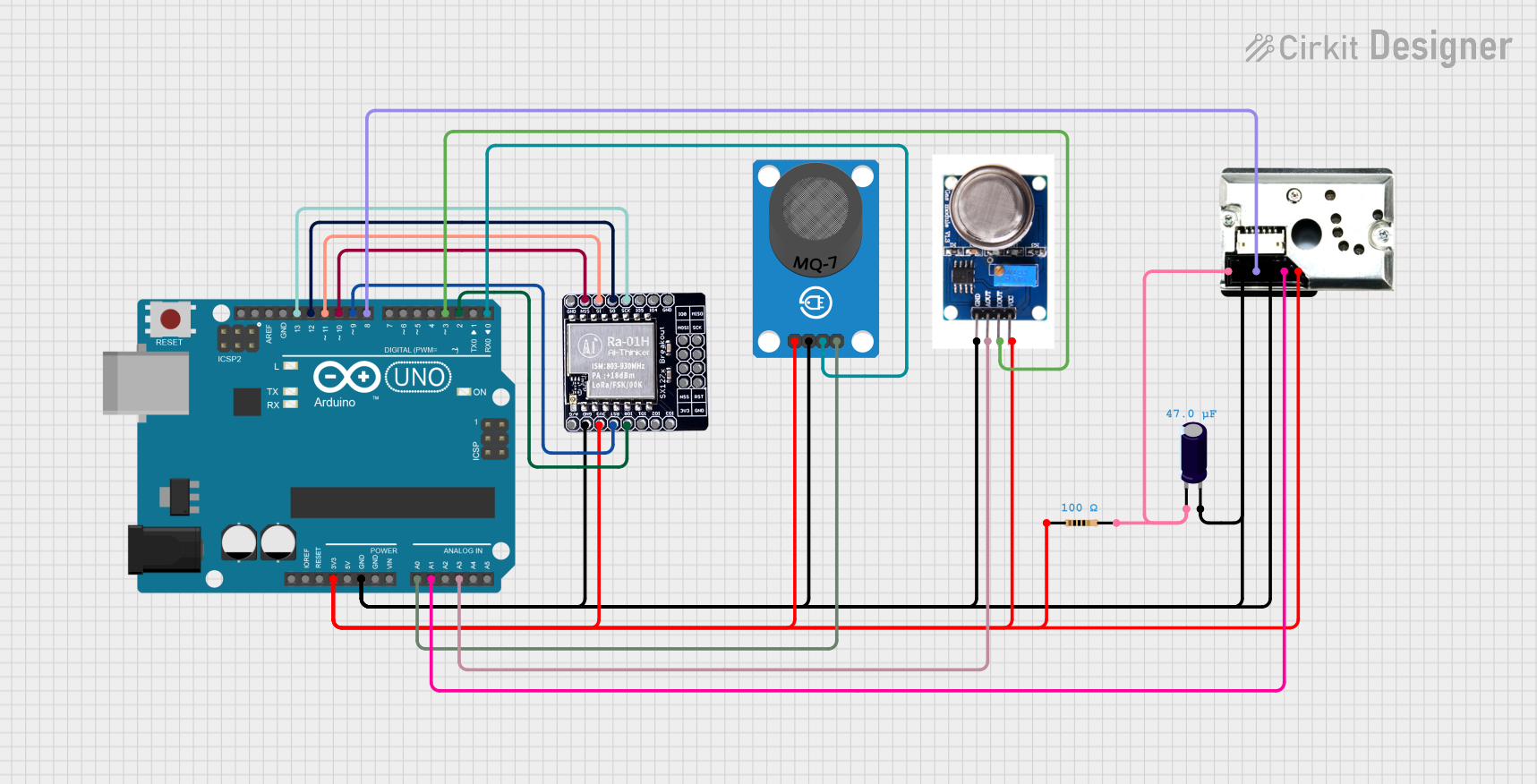
Example Code for Arduino UNO

#include <SPI.h>
#include <LoRa.h>

// Define the LoRa module pins
#define SS      10  // NSS
#define RST     9   // RESET
#define DI0     2   // DIO0

void setup() {
  Serial.begin(9600);
  while (!Serial);

  // Initialize LoRa module
  LoRa.setPins(SS, RST, DI0);
  if (!LoRa.begin(915E6)) { // Start LoRa using the frequency for your region
    Serial.println("Starting LoRa failed!");
    while (1);
  }
}

void loop() {
  // Send a message
  LoRa.beginPacket();
  LoRa.print("Hello, LoRa!");
  LoRa.endPacket();

  // Wait for a second before sending the next message
  delay(1000);
}

Troubleshooting and FAQs

Common Issues

  • No Communication: Ensure that the SPI connections are correct and the antenna is properly connected.
  • Short Range: Check the antenna placement and orientation. Also, verify that you are using the correct frequency band.
  • High Power Consumption: Make sure that the module is in sleep mode when not transmitting to save power.

Solutions and Tips for Troubleshooting

  • Double-check wiring and solder joints for any loose connections or shorts.
  • Use a logic analyzer or oscilloscope to verify SPI communication.
  • Ensure that the module's firmware is up to date and correctly configured for your application.

FAQs

Q: Can I use LoRa for real-time applications? A: LoRa is designed for low data rate applications and may not be suitable for real-time communication due to its inherent latency.

Q: Is LoRa secure? A: LoRa includes built-in encryption using AES-128, but additional security measures should be implemented at the application layer.

Q: How many devices can communicate in a LoRa network? A: LoRa networks can support thousands of devices, but the exact number depends on the network architecture and application requirements.

Q: Can I use LoRa modules from different manufacturers together? A: Yes, as long as they comply with the LoRaWAN standard and are configured to operate on the same frequency and settings.