How to Use MCB 1 Phase: Examples, Pinouts, and Specs
Introduction
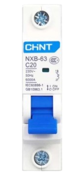
A Miniature Circuit Breaker (MCB) is an essential safety device designed to protect electrical circuits from damage caused by overcurrent or short circuits. The MCB 1 Phase is specifically designed for single-phase circuits, commonly used in residential, commercial, and industrial applications. It automatically disconnects the circuit when excessive current flows, preventing potential hazards such as overheating, fire, or equipment damage.
Explore Projects Built with MCB 1 Phase


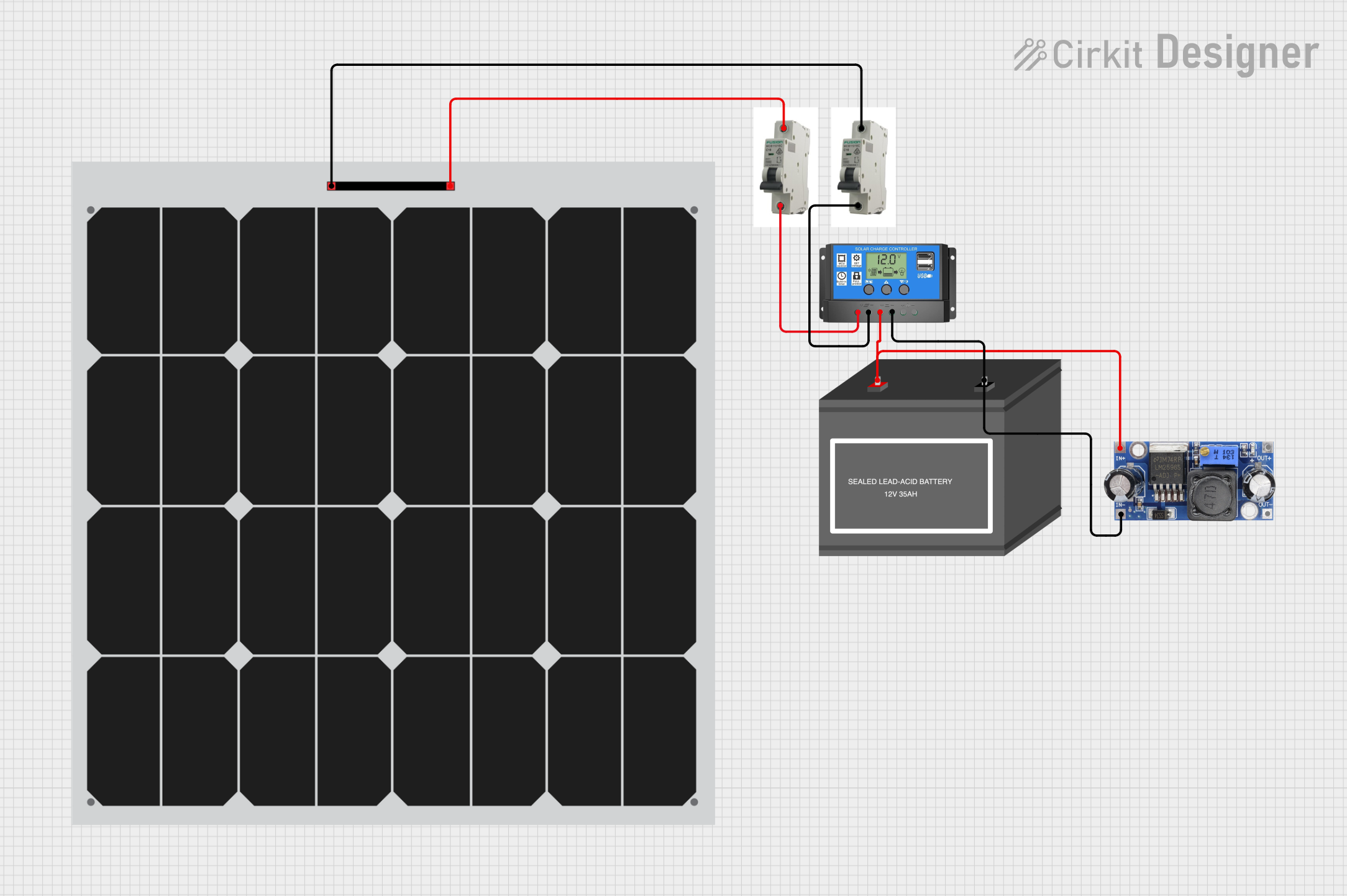
Explore Projects Built with MCB 1 Phase
Common Applications and Use Cases
- Residential electrical systems for lighting and power outlets
- Industrial machinery with single-phase power requirements
- Commercial buildings for protecting appliances and equipment
- Renewable energy systems, such as solar inverters
- Backup power systems, including UPS and generators
Technical Specifications
Key Technical Details
| Parameter | Specification |
|---|---|
| Rated Voltage | 230V AC |
| Rated Current | 6A, 10A, 16A, 20A, 32A (varies by model) |
| Breaking Capacity | 6kA |
| Frequency | 50/60 Hz |
| Number of Poles | 1 (Single Phase) |
| Tripping Curve | B, C, or D (depending on model) |
| Operating Temperature | -5°C to +40°C |
| Mounting Type | DIN Rail (35mm) |
| Standards Compliance | IEC 60898-1, IS/IEC 60947-2 |
Pin Configuration and Descriptions
The MCB 1 Phase has two primary connection points:
| Pin/Terminal | Description |
|---|---|
| Line (Input) | Connects to the incoming live wire from the power source. |
| Load (Output) | Connects to the outgoing live wire leading to the load. |
Note: The neutral wire bypasses the MCB and connects directly to the load.
Usage Instructions
How to Use the MCB 1 Phase in a Circuit
Mounting the MCB:
- Install the MCB on a standard 35mm DIN rail in the distribution box.
- Ensure the MCB is securely locked into place.
Wiring the MCB:
- Connect the live wire from the power source to the
Line (Input)terminal. - Connect the live wire leading to the load to the
Load (Output)terminal. - Tighten the terminal screws to ensure a secure connection.
- Connect the live wire from the power source to the
Testing the MCB:
- After installation, switch on the MCB and verify that the circuit operates normally.
- Use the test button (if available) to simulate a fault and ensure the MCB trips correctly.
Resetting the MCB:
- In the event of a trip, identify and resolve the cause of the overcurrent or short circuit.
- Flip the MCB switch to the "OFF" position, then back to the "ON" position to reset it.
Important Considerations and Best Practices
- Always ensure the MCB's rated current matches the circuit's load requirements.
- Do not exceed the MCB's breaking capacity (6kA) to avoid damage.
- Regularly inspect the MCB for signs of wear, overheating, or loose connections.
- Avoid using an MCB with damaged or corroded terminals.
- For circuits connected to sensitive equipment, consider using an MCB with a "B" tripping curve for faster response.
Arduino UNO Integration
While MCBs are not directly connected to microcontrollers like the Arduino UNO, they can be used in circuits that power Arduino-based systems. For example, an MCB can protect the power supply line feeding an Arduino project.
Here is an example of Arduino code to monitor the power status of a circuit protected by an MCB using a digital input pin:
// Arduino code to monitor the power status of a circuit
// connected to an MCB. A digital input pin is used to detect
// whether the MCB is supplying power to the load.

const int powerStatusPin = 2; // Pin connected to the power status signal
const int ledPin = 13;        // Built-in LED to indicate power status

void setup() {
  pinMode(powerStatusPin, INPUT); // Set the power status pin as input
  pinMode(ledPin, OUTPUT);        // Set the LED pin as output
  Serial.begin(9600);            // Initialize serial communication
}

void loop() {
  int powerStatus = digitalRead(powerStatusPin); // Read the power status

  if (powerStatus == HIGH) {
    // Power is ON
    digitalWrite(ledPin, HIGH); // Turn on the LED
    Serial.println("Power is ON");
  } else {
    // Power is OFF
    digitalWrite(ledPin, LOW);  // Turn off the LED
    Serial.println("Power is OFF");
  }

  delay(1000); // Wait for 1 second before checking again
}
Note: To use this code, you need a circuit that provides a HIGH signal (5V) to the powerStatusPin when the MCB is supplying power and a LOW signal (0V) when it is not.
Troubleshooting and FAQs
Common Issues and Solutions
| Issue | Possible Cause | Solution |
|---|---|---|
| MCB trips frequently | Overloaded circuit | Reduce the load or use an MCB with a higher rated current. |
| MCB does not trip during a fault | Faulty MCB or incorrect wiring | Replace the MCB or verify the wiring connections. |
| MCB cannot be reset | Persistent fault in the circuit | Identify and fix the fault before resetting the MCB. |
| Terminals overheating | Loose connections or excessive current | Tighten the terminals or reduce the load. |
FAQs
Can I use an MCB 1 Phase for a three-phase circuit?
- No, the MCB 1 Phase is designed specifically for single-phase circuits. For three-phase circuits, use a three-phase MCB.
What is the difference between tripping curves B, C, and D?
- Tripping curves define the MCB's response to overcurrent:
- B Curve: Trips at 3-5 times the rated current (suitable for residential use).
- C Curve: Trips at 5-10 times the rated current (used for commercial and industrial applications).
- D Curve: Trips at 10-20 times the rated current (used for heavy machinery).
- Tripping curves define the MCB's response to overcurrent:
How do I select the right MCB for my circuit?
- Consider the circuit's voltage, current, and load type. Ensure the MCB's rated current and breaking capacity match the circuit's requirements.
Can an MCB protect against electric shocks?
- No, an MCB protects against overcurrent and short circuits. For protection against electric shocks, use a Residual Current Device (RCD) or a combination of MCB and RCD.
By following this documentation, you can safely and effectively use the MCB 1 Phase in your electrical systems.