
How to Use RFduino SMD: Examples, Pinouts, and Specs
 Design with RFduino SMD in Cirkit Designer
Introduction
The RFduino SMD is a compact, low-power microcontroller with integrated Bluetooth Low Energy (BLE) capabilities. Manufactured by RFduino, this module is specifically designed for Internet of Things (IoT) applications, wearable devices, and other projects requiring wireless communication in a small form factor. Its ease of use, Arduino compatibility, and energy efficiency make it a popular choice for developers and hobbyists alike.
Explore Projects Built with RFduino SMD
 Open Project in Cirkit Designer
 Open Project in Cirkit Designer
 Open Project in Cirkit Designer
 Open Project in Cirkit Designer
Explore Projects Built with RFduino SMD
Open Project in Cirkit DesignerOpen Project in Cirkit DesignerOpen Project in Cirkit DesignerOpen Project in Cirkit DesignerCommon Applications and Use Cases
- IoT devices and smart home automation
- Wearable technology (e.g., fitness trackers, health monitors)
- Wireless sensors and data loggers
- Remote control systems
- Prototyping BLE-enabled devices
Technical Specifications
The RFduino SMD is built to deliver reliable performance while maintaining a low power profile. Below are its key technical specifications:
| Specification | Details |
|---|---|
| Microcontroller | ARM Cortex-M0, 32-bit |
| Clock Speed | 16 MHz |
| Flash Memory | 128 KB |
| RAM | 8 KB |
| Operating Voltage | 1.9V to 3.6V |
| BLE Version | Bluetooth 4.0 Low Energy |
| Communication Protocols | BLE, UART, SPI, I2C |
| GPIO Pins | 7 (configurable as digital I/O, PWM, or analog inputs) |
| Analog Input Resolution | 10-bit |
| Power Consumption | ~2.5 µA in sleep mode, ~8.5 mA during BLE transmission |
| Dimensions | 13.5 mm x 26.5 mm |
Pin Configuration and Descriptions
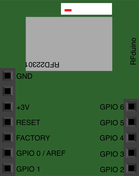
The RFduino SMD has a simple pinout, making it easy to integrate into various projects. Below is the pin configuration:
| Pin | Name | Description |
|---|---|---|
| 1 | GND | Ground connection |
| 2 | VCC | Power supply input (1.9V to 3.6V) |
| 3 | GPIO0 | General-purpose I/O pin (can also be used as an analog input or PWM output) |
| 4 | GPIO1 | General-purpose I/O pin (can also be used as an analog input or PWM output) |
| 5 | GPIO2 | General-purpose I/O pin (can also be used as an analog input or PWM output) |
| 6 | GPIO3 | General-purpose I/O pin (can also be used as an analog input or PWM output) |
| 7 | GPIO4 | General-purpose I/O pin (can also be used as an analog input or PWM output) |
| 8 | GPIO5 | General-purpose I/O pin (can also be used as an analog input or PWM output) |
| 9 | GPIO6 | General-purpose I/O pin (can also be used as an analog input or PWM output) |
| 10 | RESET | Reset pin (active low) |
Usage Instructions
The RFduino SMD is designed to be user-friendly and can be programmed using the Arduino IDE. Below are the steps to use the RFduino SMD in a circuit:
1. Setting Up the RFduino SMD
- Connect the VCC pin to a power source (1.9V to 3.6V) and the GND pin to ground.
- Use the GPIO pins for digital I/O, analog input, or PWM output as needed.
- For BLE communication, ensure the RFduino SMD is within range of the target device (typically up to 30 meters).
2. Programming the RFduino SMD
- Install the RFduino board package in the Arduino IDE:
- Open the Arduino IDE and go to File > Preferences.
- Add the RFduino board URL to the "Additional Board Manager URLs" field:
https://rfduino.com/package_rfduino_index.json - Go to Tools > Board > Boards Manager, search for "RFduino," and install the package.
- Select the RFduino board from the Tools > Board menu.
- Connect the RFduino SMD to your computer using a compatible USB-to-serial adapter.
- Write your code and upload it to the RFduino SMD.
3. Example Code: Blink an LED
The following example demonstrates how to blink an LED connected to GPIO0:
// Blink an LED connected to GPIO0 on the RFduino SMD

void setup() {
  pinMode(0, OUTPUT); // Set GPIO0 as an output pin
}

void loop() {
  digitalWrite(0, HIGH); // Turn the LED on
  delay(1000);           // Wait for 1 second
  digitalWrite(0, LOW);  // Turn the LED off
  delay(1000);           // Wait for 1 second
}
4. Important Considerations
- Ensure the power supply voltage does not exceed 3.6V to avoid damaging the module.
- Use appropriate pull-up or pull-down resistors for GPIO pins if required.
- For BLE communication, configure the RFduino SMD as a central or peripheral device based on your application.
Troubleshooting and FAQs
Common Issues and Solutions
The RFduino SMD is not detected in the Arduino IDE.
- Ensure the RFduino board package is installed correctly in the Arduino IDE.
- Verify that the USB-to-serial adapter is properly connected and the correct COM port is selected.
BLE communication is not working.
- Check that the RFduino SMD is within range of the target BLE device.
- Ensure the BLE device is in pairing mode and compatible with Bluetooth 4.0.
The module is overheating.
- Verify that the input voltage does not exceed 3.6V.
- Check for short circuits in your wiring.
The GPIO pins are not functioning as expected.
- Confirm that the pins are configured correctly in your code (e.g., as input or output).
- Test the pins individually to isolate the issue.
FAQs
Q: Can the RFduino SMD be powered by a coin cell battery?
A: Yes, the RFduino SMD can be powered by a coin cell battery, as long as the voltage is within the 1.9V to 3.6V range.
Q: Is the RFduino SMD compatible with other Arduino libraries?
A: Many Arduino libraries are compatible with the RFduino SMD, but some may require modifications due to differences in hardware architecture.
Q: What is the maximum range for BLE communication?
A: The typical range for BLE communication is up to 30 meters in open environments, but this may vary depending on obstacles and interference.
Q: Can I use the RFduino SMD for low-power applications?
A: Yes, the RFduino SMD is optimized for low-power applications, consuming as little as ~2.5 µA in sleep mode.