How to Use T-SIM7000G edited: Examples, Pinouts, and Specs
Introduction
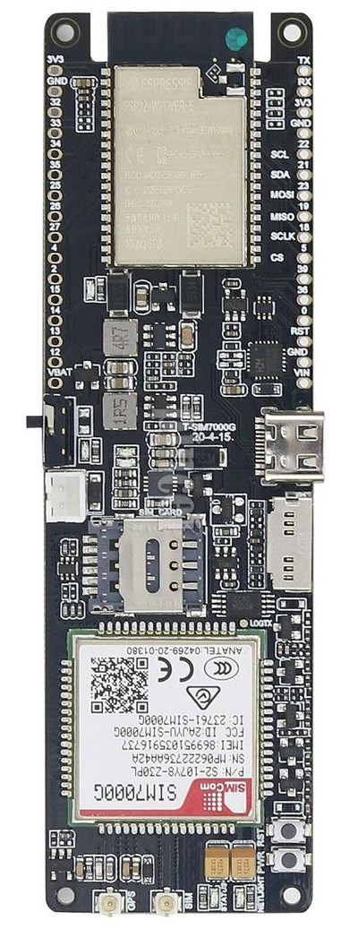
The T-SIM7000G is a versatile GSM/GPRS module manufactured by ESP32, designed for IoT (Internet of Things) applications. It supports multiple communication protocols, including LTE, and features low power consumption, making it ideal for battery-powered devices. Additionally, the module includes GPS functionality, enabling location tracking and navigation capabilities. The T-SIM7000G is widely used in applications such as smart metering, asset tracking, environmental monitoring, and remote data collection.
Explore Projects Built with T-SIM7000G edited


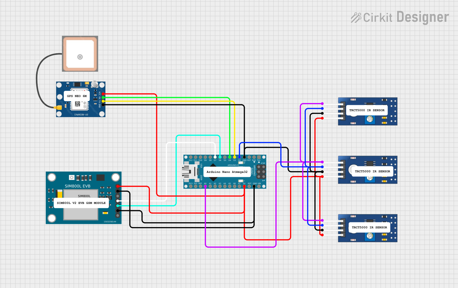
Explore Projects Built with T-SIM7000G edited
Technical Specifications
The T-SIM7000G module is packed with features that make it suitable for a wide range of IoT applications. Below are its key technical specifications:
General Specifications
- Manufacturer: ESP32
- Communication Protocols: GSM, GPRS, LTE Cat-M1, NB-IoT
- GPS Support: Yes (GNSS functionality)
- Power Supply Voltage: 3.4V to 4.2V (typical 3.8V)
- Power Consumption:
- Idle: ~1.2mA (low power mode)
- Active: ~300mA (transmitting)
- Operating Temperature: -40°C to +85°C
- Dimensions: 24mm x 24mm
Pin Configuration and Descriptions
The T-SIM7000G module has a variety of pins for power, communication, and control. Below is the pinout description:
| Pin Name | Type | Description |
|---|---|---|
| VCC | Power Input | Main power supply (3.4V to 4.2V). |
| GND | Ground | Ground connection. |
| TXD | Digital Output | UART Transmit pin for serial communication. |
| RXD | Digital Input | UART Receive pin for serial communication. |
| PWRKEY | Digital Input | Power key to turn the module on/off. |
| NET_STATUS | Digital Output | Indicates network status (e.g., connected/disconnected). |
| GPS_TX | Digital Output | UART Transmit pin for GPS data. |
| GPS_RX | Digital Input | UART Receive pin for GPS data. |
| RESET | Digital Input | Resets the module when pulled low. |
| ADC | Analog Input | Analog-to-digital converter input. |
Usage Instructions
The T-SIM7000G module can be integrated into a circuit for IoT applications. Below are the steps and best practices for using the module:
Basic Setup
Power Supply:
- Connect the VCC pin to a stable 3.8V power source.
- Ensure the GND pin is connected to the ground of the circuit.
Serial Communication:
- Connect the TXD pin of the module to the RX pin of your microcontroller (e.g., Arduino UNO).
- Connect the RXD pin of the module to the TX pin of your microcontroller.
Powering On:
- Pull the PWRKEY pin low for at least 1 second to turn on the module.
Antenna Connection:
- Attach a compatible antenna to the module for GSM and GPS functionality.
Example: Using T-SIM7000G with Arduino UNO
Below is an example code to send an SMS using the T-SIM7000G module with an Arduino UNO:
#include <SoftwareSerial.h>

// Define RX and TX pins for SoftwareSerial
SoftwareSerial sim7000(7, 8); // RX = 7, TX = 8

void setup() {
  // Initialize serial communication
  Serial.begin(9600); // For debugging
  sim7000.begin(9600); // For T-SIM7000G communication

  Serial.println("Initializing T-SIM7000G...");

  // Power on the module
  pinMode(9, OUTPUT); // PWRKEY connected to pin 9
  digitalWrite(9, LOW);
  delay(1000); // Hold PWRKEY low for 1 second
  digitalWrite(9, HIGH);

  delay(5000); // Wait for the module to initialize

  // Send AT command to check communication
  sim7000.println("AT");
  delay(1000);
  while (sim7000.available()) {
    Serial.write(sim7000.read());
  }

  // Send SMS
  sim7000.println("AT+CMGF=1"); // Set SMS mode to text
  delay(1000);
  sim7000.println("AT+CMGS=\"+1234567890\""); // Replace with recipient's number
  delay(1000);
  sim7000.println("Hello from T-SIM7000G!"); // SMS content
  sim7000.write(26); // Send Ctrl+Z to send the SMS
  delay(5000);
}

void loop() {
  // Nothing to do here
}
Best Practices
- Use a stable power supply to avoid unexpected resets or malfunctions.
- Ensure proper antenna placement for optimal GSM and GPS signal reception.
- Use level shifters if interfacing with a 5V microcontroller, as the module operates at 3.3V logic levels.
- Avoid placing the module near high-frequency noise sources to prevent interference.
Troubleshooting and FAQs
Common Issues and Solutions
Module Not Powering On:
- Ensure the PWRKEY pin is pulled low for at least 1 second during startup.
- Verify the power supply voltage is within the specified range (3.4V to 4.2V).
No Network Connection:
- Check the antenna connection and ensure it is securely attached.
- Verify that the SIM card is properly inserted and activated.
- Use the
AT+CSQcommand to check signal strength.
GPS Not Working:
- Ensure the GPS antenna is connected and placed in an open area with a clear view of the sky.
- Use the
AT+CGNSPWR=1command to enable GPS functionality.
Serial Communication Issues:
- Confirm the baud rate of the module matches the microcontroller's settings.
- Check the wiring of the TX and RX pins.
FAQs
Q: Can the T-SIM7000G operate on 5V logic levels?
A: No, the module operates at 3.3V logic levels. Use level shifters if interfacing with a 5V microcontroller.Q: How do I check the module's firmware version?
A: Use theAT+CGMRcommand to retrieve the firmware version.Q: What is the maximum data rate supported by the module?
A: The T-SIM7000G supports a maximum data rate of 375kbps for LTE Cat-M1 and 32kbps for NB-IoT.Q: Can I use the module for voice calls?
A: Yes, the T-SIM7000G supports voice calls in addition to SMS and data communication.
By following this documentation, users can effectively integrate and utilize the T-SIM7000G module in their IoT projects.