Cirkit Designer
Your all-in-one circuit design IDE
Home /
Component Documentation
How to Use keypad: Examples, Pinouts, and Specs
Introduction
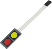
A keypad is an input device consisting of a set of buttons arranged in a block or 'pad' which bear digits, symbols, or alphabetical letters. It is used to input data into a system, often for security or user interface purposes. Keypads are commonly found in devices such as telephones, calculators, ATMs, and access control systems.
Explore Projects Built with keypad
Arduino UNO Keypad-Controlled LED and Buzzer System with RTC and Bluetooth

This circuit is an Arduino-based keypad interface system that reads input from a 4x4 membrane matrix keypad and displays the pressed key on the serial monitor. It also includes a real-time clock (RTC) module, a Bluetooth module, and visual indicators using red and green LEDs. Additionally, a buzzer is controlled via an NPN transistor for audio feedback.
Arduino UNO Keypad Input Logger

This circuit integrates a 4x4 keypad with an Arduino UNO to create a simple input interface. The Arduino reads key presses from the keypad and outputs the corresponding character to the Serial Monitor, allowing for user interaction and data entry.
Arduino UNO Membrane Keypad Interface
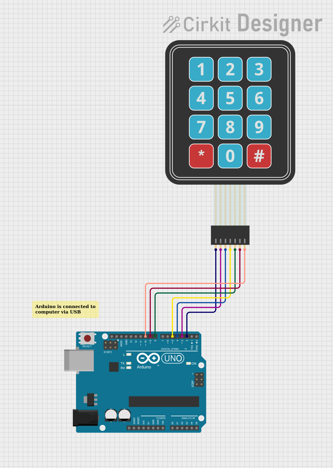
This circuit connects a 3x4 membrane matrix keypad to an Arduino UNO microcontroller. The Arduino is programmed to detect and report keypress events from the keypad over a serial connection at a baud rate of 9600. The purpose of this circuit is to interface with the keypad and provide a way to input data into a system or control a device.
Arduino UNO Based NFC Reader with Membrane Keypad Interface
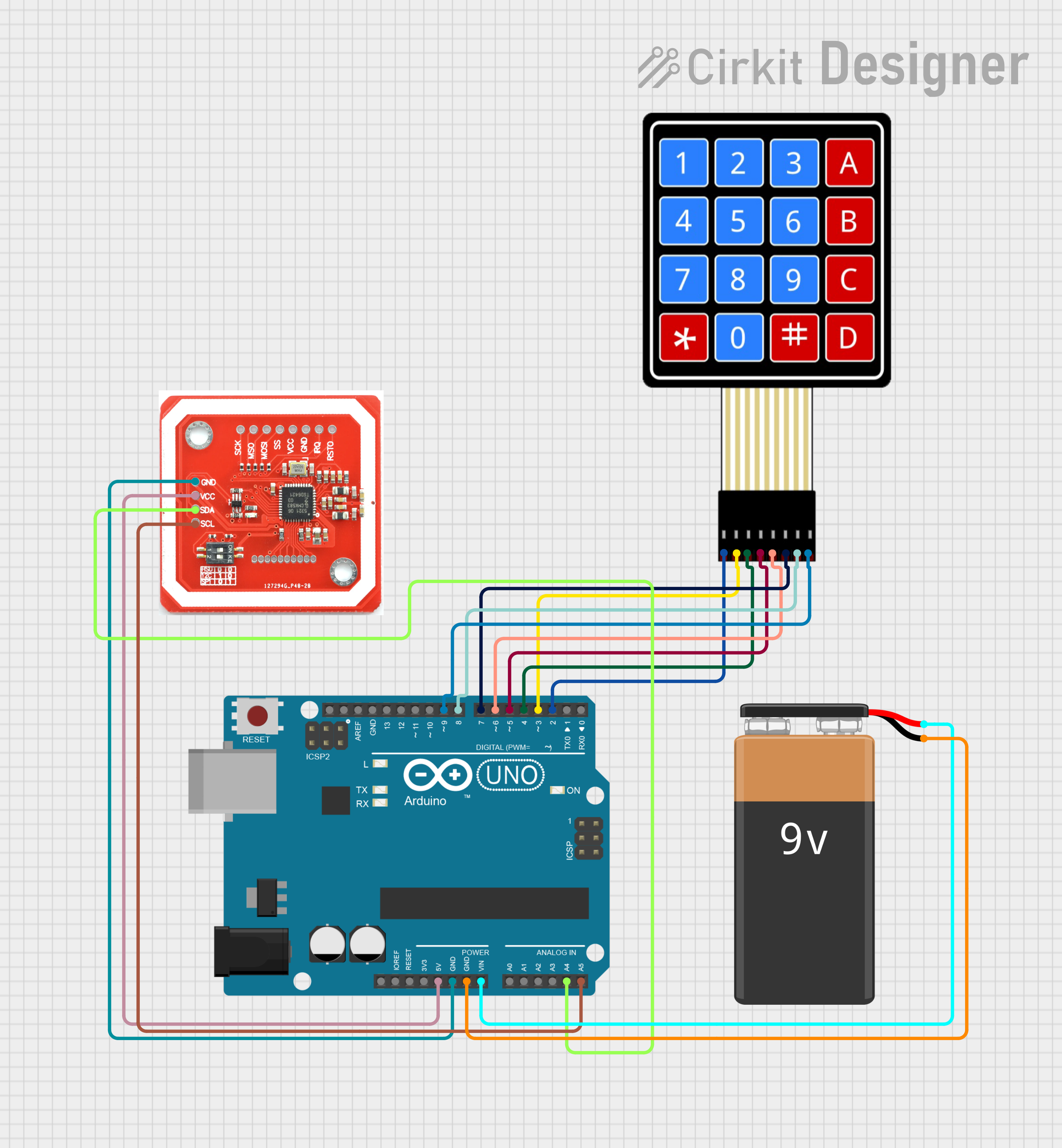
This circuit features an Arduino UNO connected to a 4x4 membrane matrix keypad, an NFC/RFID reader, and powered by a 9V battery. The Arduino is programmed to detect and display keypad inputs and read NFC tags, likely for an access control or identification system. The NFC/RFID reader communicates with the Arduino via I2C (using SDA and SCL lines), and the keypad is interfaced using digital IO pins.
Explore Projects Built with keypad
Arduino UNO Keypad-Controlled LED and Buzzer System with RTC and Bluetooth
This circuit is an Arduino-based keypad interface system that reads input from a 4x4 membrane matrix keypad and displays the pressed key on the serial monitor. It also includes a real-time clock (RTC) module, a Bluetooth module, and visual indicators using red and green LEDs. Additionally, a buzzer is controlled via an NPN transistor for audio feedback.
Arduino UNO Keypad Input Logger
This circuit integrates a 4x4 keypad with an Arduino UNO to create a simple input interface. The Arduino reads key presses from the keypad and outputs the corresponding character to the Serial Monitor, allowing for user interaction and data entry.
Arduino UNO Membrane Keypad Interface
This circuit connects a 3x4 membrane matrix keypad to an Arduino UNO microcontroller. The Arduino is programmed to detect and report keypress events from the keypad over a serial connection at a baud rate of 9600. The purpose of this circuit is to interface with the keypad and provide a way to input data into a system or control a device.
Arduino UNO Based NFC Reader with Membrane Keypad Interface
This circuit features an Arduino UNO connected to a 4x4 membrane matrix keypad, an NFC/RFID reader, and powered by a 9V battery. The Arduino is programmed to detect and display keypad inputs and read NFC tags, likely for an access control or identification system. The NFC/RFID reader communicates with the Arduino via I2C (using SDA and SCL lines), and the keypad is interfaced using digital IO pins.
Technical Specifications
Key Technical Details
| Parameter | Value |
|---|---|
| Operating Voltage | 3.3V - 5V |
| Operating Current | 10mA - 20mA |
| Number of Keys | 12 (3x4) or 16 (4x4) |
| Keypad Type | Matrix |
| Contact Resistance | < 100Ω |
| Insulation Resistance | > 100MΩ |
| Operating Temperature | -20°C to +50°C |
Pin Configuration and Descriptions
3x4 Keypad
| Pin Number | Pin Name | Description |
|---|---|---|
| 1 | R1 | Row 1 |
| 2 | R2 | Row 2 |
| 3 | R3 | Row 3 |
| 4 | R4 | Row 4 (if applicable) |
| 5 | C1 | Column 1 |
| 6 | C2 | Column 2 |
| 7 | C3 | Column 3 |
| 8 | C4 | Column 4 (if applicable) |
4x4 Keypad
| Pin Number | Pin Name | Description |
|---|---|---|
| 1 | R1 | Row 1 |
| 2 | R2 | Row 2 |
| 3 | R3 | Row 3 |
| 4 | R4 | Row 4 |
| 5 | C1 | Column 1 |
| 6 | C2 | Column 2 |
| 7 | C3 | Column 3 |
| 8 | C4 | Column 4 |
Usage Instructions
How to Use the Keypad in a Circuit
Connect the Keypad to the Microcontroller:
- For a 3x4 keypad, connect the 7 pins (R1, R2, R3, C1, C2, C3) to the digital I/O pins of the microcontroller.
- For a 4x4 keypad, connect the 8 pins (R1, R2, R3, R4, C1, C2, C3, C4) to the digital I/O pins of the microcontroller.
Initialize the Keypad Library:
- Use a keypad library (e.g., Keypad.h for Arduino) to manage the keypad inputs.
Read Key Presses:
- Use the library functions to detect and read key presses.
Important Considerations and Best Practices
- Debouncing: Keypads may produce multiple signals for a single key press due to mechanical bouncing. Use software debouncing techniques to filter out these unwanted signals.
- Pull-up Resistors: Ensure that the microcontroller's input pins are configured with internal pull-up resistors to avoid floating inputs.
- Shielding: If the keypad is used in a noisy environment, consider shielding the keypad and its connections to prevent interference.
Example Code for Arduino UNO
#include <Keypad.h>

// Define the size of the keypad
const byte ROWS = 4; // Four rows
const byte COLS = 4; // Four columns

// Define the keymap
char keys[ROWS][COLS] = {
  {'1','2','3','A'},
  {'4','5','6','B'},
  {'7','8','9','C'},
  {'*','0','#','D'}
};

// Connect keypad ROW0, ROW1, ROW2, ROW3 to these Arduino pins
byte rowPins[ROWS] = {9, 8, 7, 6};

// Connect keypad COL0, COL1, COL2, COL3 to these Arduino pins
byte colPins[COLS] = {5, 4, 3, 2};

// Create the Keypad object
Keypad keypad = Keypad(makeKeymap(keys), rowPins, colPins, ROWS, COLS);

void setup() {
  Serial.begin(9600); // Initialize serial communication
}

void loop() {
  char key = keypad.getKey(); // Get the key pressed

  if (key) { // If a key is pressed
    Serial.println(key); // Print the key to the serial monitor
  }
}
Troubleshooting and FAQs
Common Issues Users Might Face
No Key Press Detected:
- Solution: Check the wiring connections between the keypad and the microcontroller. Ensure that the correct pins are used and that they are firmly connected.
Multiple Key Presses Detected:
- Solution: Implement debouncing in the software to filter out spurious signals caused by mechanical bouncing.
Incorrect Key Detected:
- Solution: Verify the keymap configuration in the code. Ensure that the keymap array matches the physical layout of the keypad.
Solutions and Tips for Troubleshooting
- Check Connections: Ensure all connections are secure and correctly mapped to the microcontroller pins.
- Use Serial Monitor: Utilize the serial monitor to debug and verify the key presses.
- Library Documentation: Refer to the keypad library documentation for additional functions and troubleshooting tips.
By following this documentation, users should be able to effectively integrate and utilize a keypad in their electronic projects, whether for simple input tasks or more complex user interfaces.