How to Use Arduino Mega 2560aym: Examples, Pinouts, and Specs
Introduction
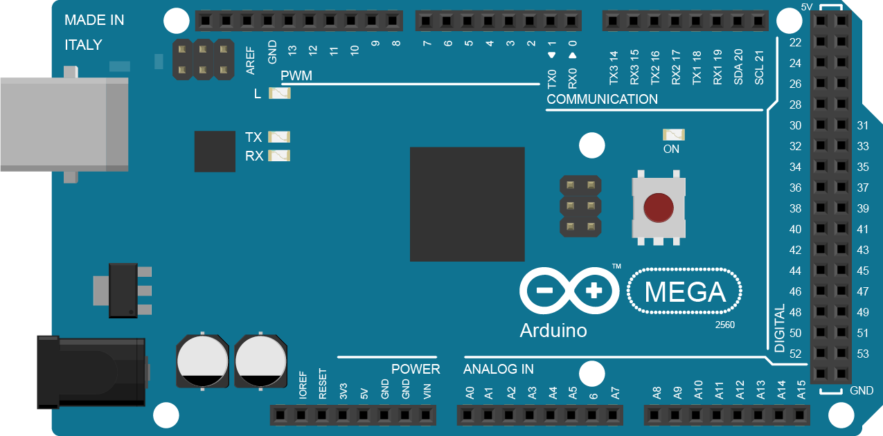
The Arduino Mega 2560 is a microcontroller board based on the ATmega2560 microcontroller. It is designed for projects requiring a large number of input/output pins, extensive memory, and robust processing power. With 54 digital input/output pins (15 of which can be used as PWM outputs), 16 analog inputs, 4 UARTs (hardware serial ports), and a USB connection for programming, the Arduino Mega 2560 is ideal for building complex projects and prototypes.
Common applications include:
- Robotics and automation systems
- IoT (Internet of Things) devices
- Data acquisition and logging
- Advanced sensor networks
- Prototyping for industrial and academic projects
Explore Projects Built with Arduino Mega 2560aym
Explore Projects Built with Arduino Mega 2560aym
Technical Specifications
The following table outlines the key technical details of the Arduino Mega 2560:
| Specification | Details |
|---|---|
| Microcontroller | ATmega2560 |
| Operating Voltage | 5V |
| Input Voltage (recommended) | 7-12V |
| Input Voltage (limit) | 6-20V |
| Digital I/O Pins | 54 (15 PWM outputs) |
| Analog Input Pins | 16 |
| DC Current per I/O Pin | 20 mA |
| Flash Memory | 256 KB (8 KB used by bootloader) |
| SRAM | 8 KB |
| EEPROM | 4 KB |
| Clock Speed | 16 MHz |
| USB Connection | Type-B USB |
| Communication Interfaces | UART, SPI, I2C |
| Dimensions | 101.52 mm x 53.3 mm |
Pin Configuration and Descriptions
The Arduino Mega 2560 has a variety of pins for different functionalities. Below is a summary of the pin configuration:
Digital Pins
| Pin Number | Function |
|---|---|
| 0-1 | UART0 (Serial RX/TX) |
| 2-13 | General-purpose I/O, PWM (2-13) |
| 14-15 | UART1 (Serial RX/TX) |
| 16-17 | UART2 (Serial RX/TX) |
| 18-19 | UART3 (Serial RX/TX) |
| 20-21 | I2C (SDA/SCL) |
| 22-53 | General-purpose I/O |
Analog Pins
| Pin Number | Function |
|---|---|
| A0-A15 | Analog input (10-bit ADC) |
Power Pins
| Pin | Function |
|---|---|
| VIN | Input voltage to the board |
| 5V | Regulated 5V output |
| 3.3V | Regulated 3.3V output |
| GND | Ground |
| IOREF | Reference voltage for I/O |
| RESET | Reset the microcontroller |
Usage Instructions
How to Use the Arduino Mega 2560 in a Circuit
Powering the Board:
- Connect the board to your computer using a USB Type-B cable for programming and power.
- Alternatively, use an external power supply (7-12V) via the VIN pin or the DC barrel jack.
Programming the Board:
- Install the Arduino IDE from the official Arduino website.
- Select "Arduino Mega 2560" as the board type in the Tools menu.
- Choose the correct COM port for the board.
- Write or load your sketch and click the "Upload" button to program the board.
Connecting Components:
- Use the digital pins for controlling LEDs, relays, or other digital devices.
- Use the analog pins to read sensor data (e.g., temperature, light).
- Use the UART, SPI, or I2C interfaces for communication with other devices.
Example Code: Blinking an LED
The following example demonstrates how to blink an LED connected to pin 13 of the Arduino Mega 2560.
// This sketch blinks an LED connected to digital pin 13
// The LED will turn on for 1 second, then off for 1 second

void setup() {
  pinMode(13, OUTPUT); // Set pin 13 as an output
}

void loop() {
  digitalWrite(13, HIGH); // Turn the LED on
  delay(1000);            // Wait for 1 second
  digitalWrite(13, LOW);  // Turn the LED off
  delay(1000);            // Wait for 1 second
}
Important Considerations and Best Practices
- Avoid exceeding the maximum current rating (20 mA) for each I/O pin to prevent damage.
- Use external pull-up or pull-down resistors for stable digital input readings.
- When using high-current devices, consider using external transistors or relays.
- Ensure proper grounding when connecting external components to avoid noise or erratic behavior.
Troubleshooting and FAQs
Common Issues and Solutions
The board is not detected by the computer:
- Ensure the USB cable is properly connected and functional.
- Install the necessary USB drivers for the Arduino Mega 2560.
- Try a different USB port or cable.
Sketch upload fails:
- Verify that the correct board and COM port are selected in the Arduino IDE.
- Press the reset button on the board before uploading.
- Check for conflicting processes using the COM port (e.g., serial monitor).
Components connected to the board are not working:
- Double-check the wiring and connections.
- Ensure the components are compatible with the Arduino Mega 2560.
- Use a multimeter to verify voltage levels and continuity.
FAQs
Q: Can I power the Arduino Mega 2560 with a battery?
A: Yes, you can use a battery with a voltage between 7-12V connected to the VIN pin or the DC barrel jack.
Q: How do I expand the number of I/O pins?
A: You can use I/O expanders like the MCP23017 or shift registers like the 74HC595 to increase the number of available pins.
Q: Is the Arduino Mega 2560 compatible with Arduino shields?
A: Yes, the Arduino Mega 2560 is compatible with most Arduino shields, but ensure the shield supports the Mega's pin layout.
Q: Can I use the Arduino Mega 2560 for wireless communication?
A: Yes, you can use wireless modules like the ESP8266, HC-05 Bluetooth module, or NRF24L01 with the Arduino Mega 2560.