How to Use potentionmeter: Examples, Pinouts, and Specs

Introduction
A potentiometer is a variable resistor that allows users to adjust voltage levels in a circuit. By varying its resistance, it enables control over current flow and signal levels. Potentiometers are widely used in applications such as volume controls, light dimmers, and as input devices in electronic circuits.
Explore Projects Built with potentionmeter
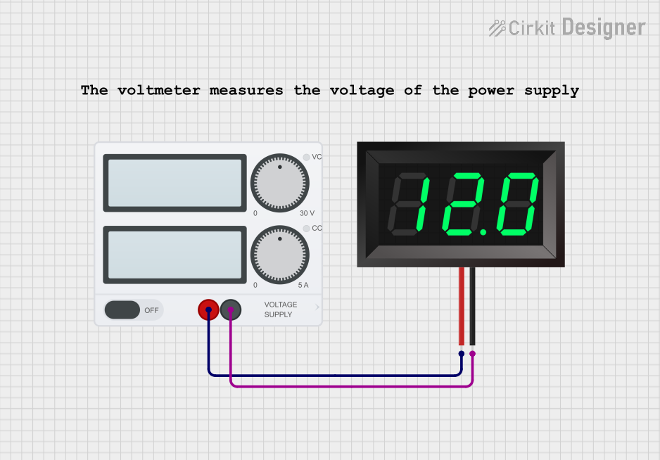
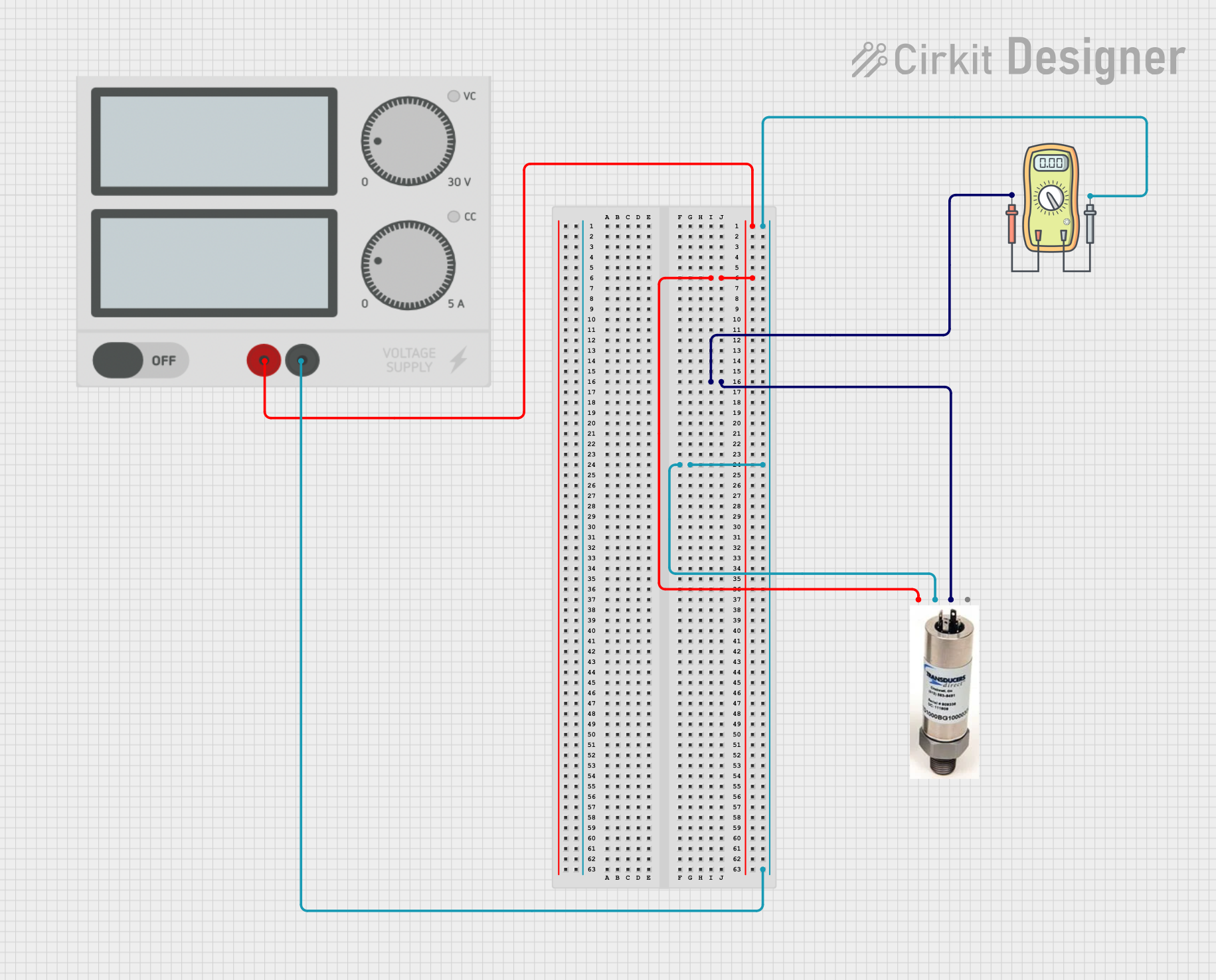
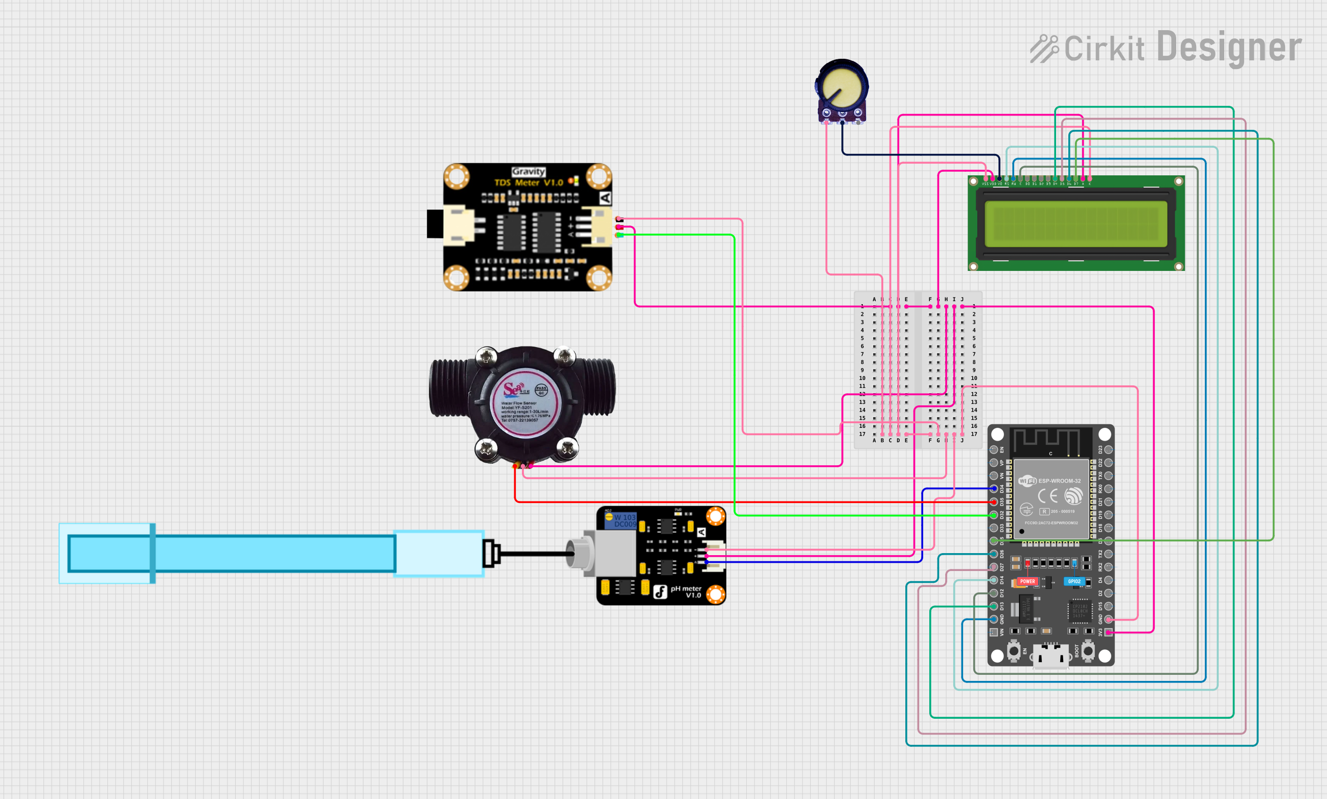
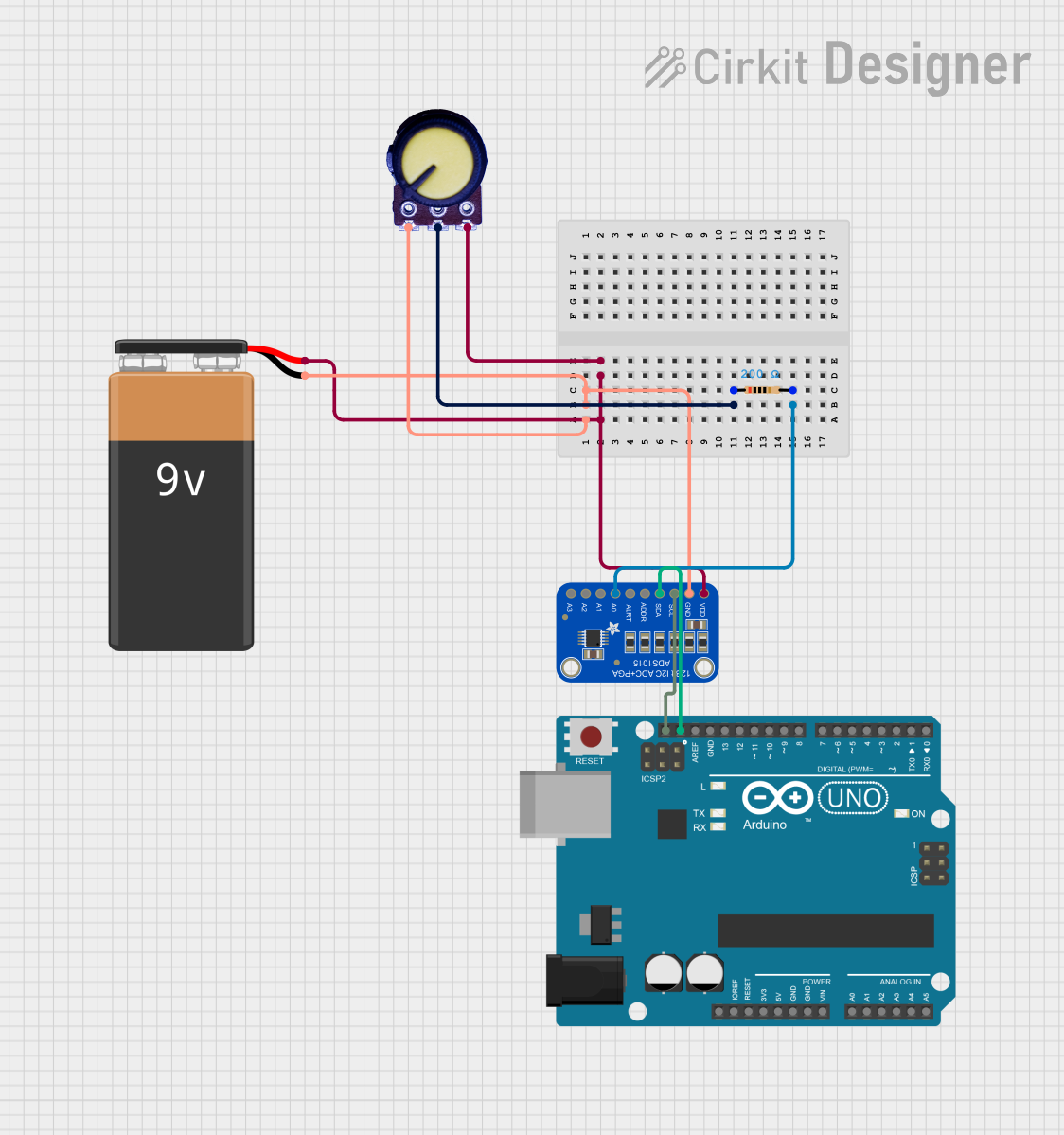
Explore Projects Built with potentionmeter
Common Applications and Use Cases
- Audio equipment for volume adjustment
- Brightness control in lighting systems
- Calibration and tuning in electronic circuits
- Position sensing in joysticks and other input devices
- Adjustable power supplies
Technical Specifications
Below are the general technical specifications for a standard potentiometer. Note that specific values may vary depending on the model and manufacturer.
| Parameter | Specification |
|---|---|
| Resistance Range | 1 kΩ to 1 MΩ |
| Power Rating | 0.1 W to 2 W |
| Tolerance | ±10% to ±20% |
| Operating Voltage | Up to 50 V DC |
| Operating Temperature | -40°C to +125°C |
| Adjustment Type | Rotary or Linear (Slider) |
| Lifespan | 10,000 to 1,000,000 cycles |
Pin Configuration and Descriptions
A potentiometer typically has three pins:
| Pin | Description |
|---|---|
| Pin 1 | One end of the resistive track (fixed resistance) |
| Pin 2 | Wiper (variable resistance output) |
| Pin 3 | Other end of the resistive track (fixed resistance) |
Usage Instructions
How to Use the Potentiometer in a Circuit
Connect the Pins:
- Connect Pin 1 to the positive voltage supply (Vcc).
- Connect Pin 3 to ground (GND).
- Connect Pin 2 (the wiper) to the input of the circuit where the variable voltage is required.
Adjust the Resistance:
- Rotate the knob (for rotary potentiometers) or slide the lever (for linear potentiometers) to change the resistance and adjust the output voltage.
Voltage Divider Configuration:
- A potentiometer can be used as a voltage divider by connecting Pin 1 to Vcc, Pin 3 to GND, and using Pin 2 as the output. The output voltage will vary based on the wiper's position.
Important Considerations and Best Practices
- Power Rating: Ensure the potentiometer's power rating is not exceeded to avoid overheating or damage.
- Mechanical Stress: Avoid applying excessive force to the knob or slider to prevent mechanical failure.
- Debouncing: When used as an input device (e.g., in Arduino projects), consider implementing software debouncing to handle noise caused by mechanical movement.
- Mounting: Secure the potentiometer properly to prevent movement or damage during operation.
Example: Using a Potentiometer with Arduino UNO
Below is an example of how to use a potentiometer to control the brightness of an LED using an Arduino UNO.
// Define pin connections
const int potPin = A0;  // Potentiometer connected to analog pin A0
const int ledPin = 9;   // LED connected to digital pin 9 (PWM pin)

void setup() {
  pinMode(ledPin, OUTPUT);  // Set LED pin as output
}

void loop() {
  int potValue = analogRead(potPin);  // Read potentiometer value (0-1023)

  // Map the potentiometer value to a PWM range (0-255)
  int ledBrightness = map(potValue, 0, 1023, 0, 255);

  analogWrite(ledPin, ledBrightness);  // Set LED brightness
}
Notes:
- Ensure the potentiometer is connected correctly to avoid incorrect readings.
- Use a current-limiting resistor with the LED to prevent damage.
Troubleshooting and FAQs
Common Issues and Solutions
No Output Voltage:
- Cause: Incorrect wiring or loose connections.
- Solution: Verify all connections and ensure the potentiometer is wired correctly.
Inconsistent or Noisy Output:
- Cause: Dust or wear on the resistive track.
- Solution: Clean the potentiometer or replace it if worn out.
Overheating:
- Cause: Exceeding the power rating.
- Solution: Use a potentiometer with a higher power rating or reduce the current in the circuit.
Mechanical Failure:
- Cause: Excessive force applied to the knob or slider.
- Solution: Handle the potentiometer gently and avoid over-tightening during installation.
FAQs
Q: Can I use a potentiometer to control AC voltage?
A: Standard potentiometers are designed for DC circuits. For AC applications, use a specialized variable transformer or dimmer circuit.
Q: How do I choose the right potentiometer for my project?
A: Consider the required resistance range, power rating, and physical size. For precise adjustments, choose a potentiometer with finer resolution.
Q: Can I use a potentiometer as a variable resistor?
A: Yes, by connecting only two pins (Pin 1 and Pin 2 or Pin 2 and Pin 3), a potentiometer can function as a variable resistor.
Q: What is the lifespan of a potentiometer?
A: The lifespan depends on the model and usage but typically ranges from 10,000 to 1,000,000 cycles.