
How to Use RFM92/95 Breakout (433MHz): Examples, Pinouts, and Specs
 Design with RFM92/95 Breakout (433MHz) in Cirkit Designer
Introduction
The RFM92/95 Breakout (433MHz) is a compact module designed for wireless communication, operating at a frequency of 433MHz. It is ideal for low-power applications such as remote sensors, Internet of Things (IoT) devices, and other wireless data transmission systems. This module features a built-in transceiver, enabling both data transmission and reception, making it a versatile choice for bidirectional communication.
Common applications include:
- Remote environmental monitoring
- Home automation systems
- Wireless sensor networks
- Industrial IoT applications
- Long-range communication for hobbyist projects
Explore Projects Built with RFM92/95 Breakout (433MHz)
 Open Project in Cirkit Designer
 Open Project in Cirkit Designer
 Open Project in Cirkit Designer
 Open Project in Cirkit Designer
Explore Projects Built with RFM92/95 Breakout (433MHz)
Open Project in Cirkit DesignerOpen Project in Cirkit DesignerOpen Project in Cirkit DesignerOpen Project in Cirkit DesignerTechnical Specifications
The RFM92/95 Breakout module is based on the Semtech SX1276/77/78/79 LoRa transceiver chip, which supports long-range communication with low power consumption. Below are the key technical details:
General Specifications
| Parameter | Value |
|---|---|
| Frequency Range | 433MHz |
| Modulation Techniques | LoRa™, FSK, GFSK, OOK |
| Output Power | Up to +20 dBm (100mW) |
| Sensitivity | Down to -148 dBm |
| Data Rate | 0.018 kbps to 37.5 kbps |
| Operating Voltage | 1.8V to 3.7V |
| Current Consumption | 10.8mA (Rx), 120mA (Tx @ +20dBm) |
| Communication Interface | SPI |
| Operating Temperature | -40°C to +85°C |
| Dimensions | 16mm x 16mm |
Pin Configuration and Descriptions
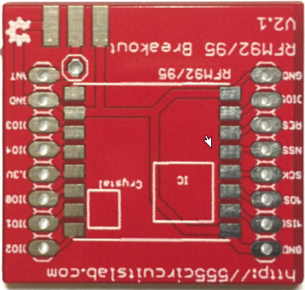
The RFM92/95 Breakout module has the following pinout:
| Pin Name | Pin Number | Description |
|---|---|---|
| GND | 1 | Ground connection |
| VCC | 2 | Power supply input (1.8V to 3.7V) |
| SCK | 3 | SPI Clock input |
| MISO | 4 | SPI Master-In-Slave-Out (data output from the module) |
| MOSI | 5 | SPI Master-Out-Slave-In (data input to the module) |
| NSS | 6 | SPI Chip Select (active low) |
| DIO0 | 7 | Digital I/O pin 0 (used for interrupts or status signaling) |
| DIO1 | 8 | Digital I/O pin 1 (used for interrupts or status signaling) |
| RESET | 9 | Reset pin (active low) |
| ANT | 10 | Antenna connection for RF signal transmission and reception |
Usage Instructions
How to Use the RFM92/95 Breakout in a Circuit
- Power Supply: Connect the VCC pin to a regulated power source (1.8V to 3.7V) and the GND pin to the ground of your circuit.
- SPI Communication: Connect the SCK, MISO, MOSI, and NSS pins to the corresponding SPI pins on your microcontroller.
- Antenna: Attach a 433MHz antenna to the ANT pin for optimal signal transmission and reception.
- Reset: Use the RESET pin to initialize the module during startup or to recover from errors.
- Digital I/O Pins: Use DIO0 and DIO1 for interrupt handling or status monitoring, as required by your application.
Important Considerations and Best Practices
- Antenna Selection: Use a high-quality 433MHz antenna to maximize range and signal quality.
- Power Supply: Ensure a stable power supply to avoid communication errors.
- SPI Configuration: Configure the SPI interface on your microcontroller to match the module's requirements (e.g., clock polarity and phase).
- LoRa Settings: Adjust the LoRa parameters (e.g., spreading factor, bandwidth, coding rate) to optimize performance for your application.
- Regulatory Compliance: Ensure compliance with local regulations for 433MHz frequency usage.
Example: Connecting to an Arduino UNO
Below is an example of how to connect the RFM92/95 Breakout to an Arduino UNO and send data using the LoRa library.
Wiring Diagram
| RFM92/95 Pin | Arduino UNO Pin |
|---|---|
| VCC | 3.3V |
| GND | GND |
| SCK | D13 |
| MISO | D12 |
| MOSI | D11 |
| NSS | D10 |
| RESET | D9 |
| DIO0 | D2 |
Arduino Code Example
#include <SPI.h>
#include <LoRa.h> // Include the LoRa library

#define NSS 10    // Chip Select pin
#define RESET 9   // Reset pin
#define DIO0 2    // DIO0 pin

void setup() {
  Serial.begin(9600); // Initialize serial communication
  while (!Serial);

  Serial.println("Initializing LoRa module...");

  // Initialize LoRa module
  LoRa.setPins(NSS, RESET, DIO0);
  if (!LoRa.begin(433E6)) { // Set frequency to 433MHz
    Serial.println("LoRa initialization failed!");
    while (1);
  }

  Serial.println("LoRa initialized successfully!");
}

void loop() {
  Serial.println("Sending packet...");
  LoRa.beginPacket();          // Start a new packet
  LoRa.print("Hello, world!"); // Add data to the packet
  LoRa.endPacket();            // Send the packet

  delay(5000); // Wait 5 seconds before sending the next packet
}
Troubleshooting and FAQs
Common Issues
No Communication with the Module
- Cause: Incorrect SPI wiring or configuration.
- Solution: Double-check the SPI connections and ensure the SPI settings on your microcontroller match the module's requirements.
Poor Signal Range
- Cause: Low-quality or mismatched antenna.
- Solution: Use a proper 433MHz antenna and ensure it is securely connected to the ANT pin.
Module Not Responding
- Cause: Insufficient power supply or incorrect RESET pin handling.
- Solution: Ensure the power supply is stable and toggle the RESET pin during initialization.
Interference with Other Devices
- Cause: Operating in a crowded frequency band.
- Solution: Adjust the LoRa parameters (e.g., spreading factor, bandwidth) to minimize interference.
FAQs
Q: Can I use the RFM92/95 Breakout with a 5V microcontroller?
A: The module operates at 1.8V to 3.7V. Use a level shifter for SPI signals if your microcontroller operates at 5V.
Q: What is the maximum range of the RFM92/95 module?
A: The range depends on environmental factors, antenna quality, and LoRa settings. In ideal conditions, it can achieve up to 10km.
Q: Can I use this module for FSK or OOK modulation?
A: Yes, the RFM92/95 supports FSK, GFSK, and OOK modulation in addition to LoRa.
Q: How do I optimize power consumption?
A: Use the module's sleep mode when not transmitting or receiving data to minimize power usage.