How to Use Battery AAx3 4.5V: Examples, Pinouts, and Specs
Introduction
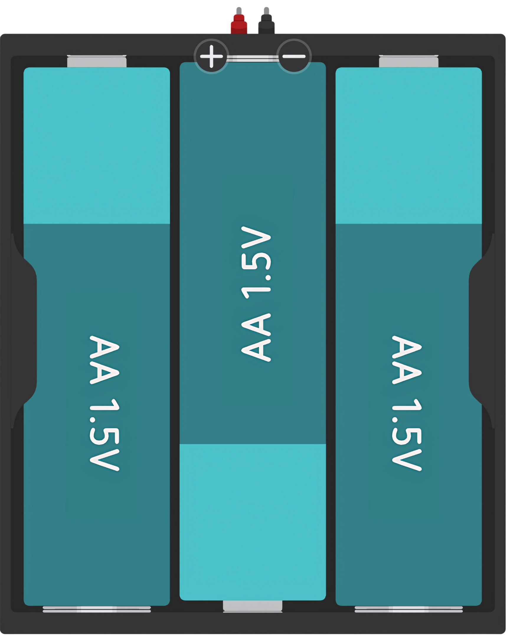
The AAx3 4.5V battery holder is a simple and essential component used to power a wide range of electronic devices and projects. It is designed to hold three AA batteries in series, providing a combined output of 4.5 volts. This type of battery holder is commonly used in portable devices, DIY electronics projects, and educational kits due to its ease of use and the widespread availability of AA batteries.
Explore Projects Built with Battery AAx3 4.5V

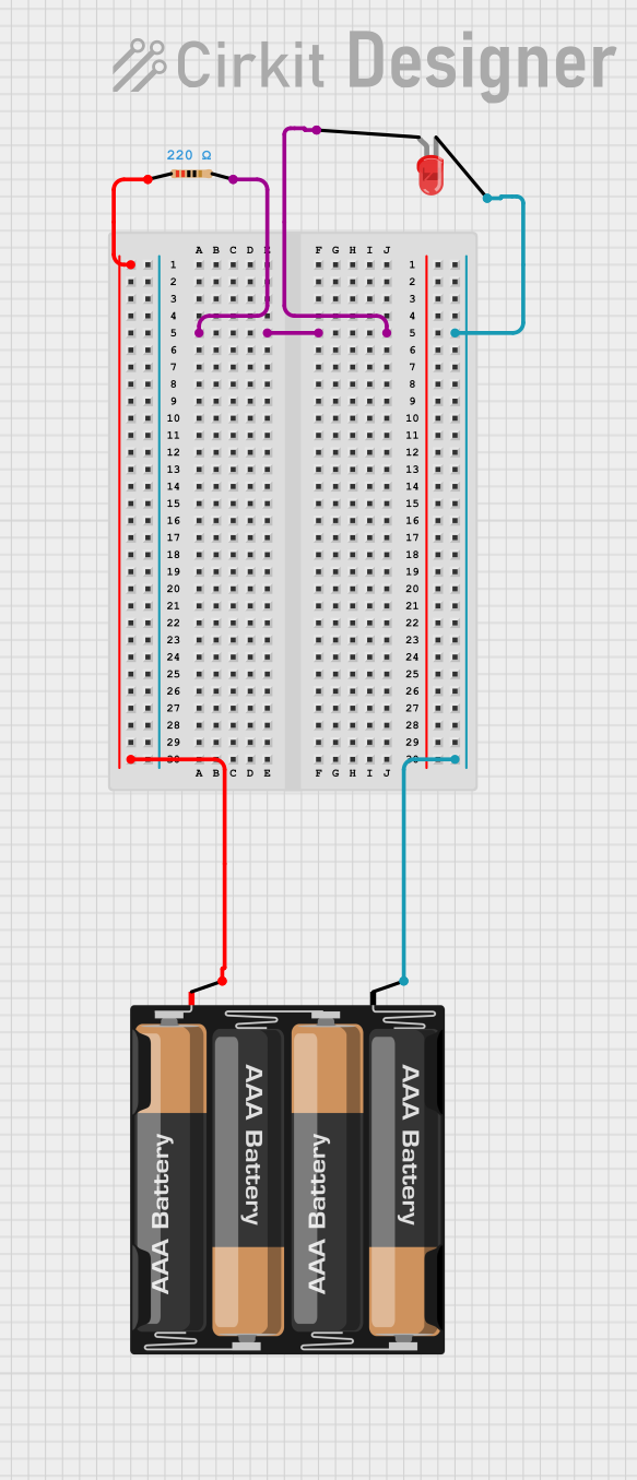
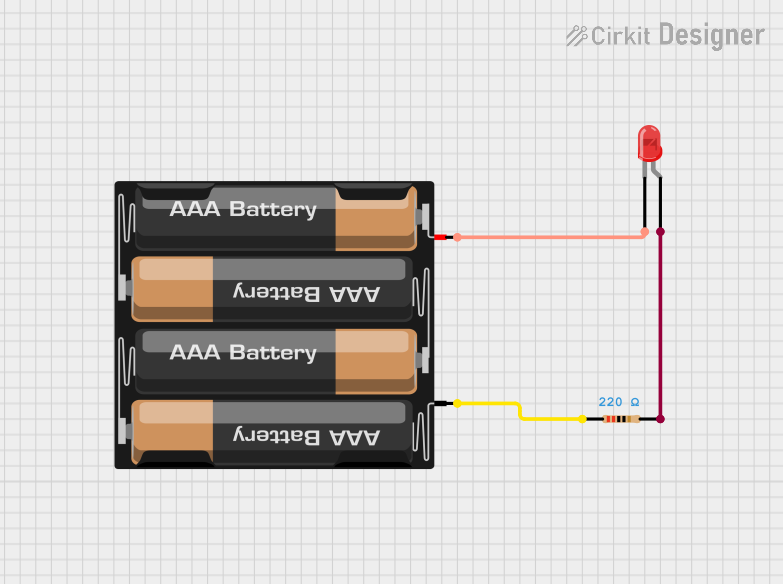
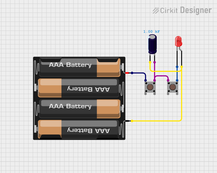
Explore Projects Built with Battery AAx3 4.5V
Common Applications and Use Cases
- Portable electronic devices
- DIY electronics projects
- Remote controls
- Educational kits and robotics
- Arduino and other microcontroller-based systems
Technical Specifications
Key Technical Details
- Nominal Voltage: 4.5V (1.5V per AA battery in series)
- Maximum Recommended Current: Varies based on the batteries used
- Material: Typically plastic casing with metal contacts
- Battery Compatibility: Standard AA size batteries (alkaline, NiMH, lithium, etc.)
Pin Configuration and Descriptions
The battery holder typically does not have a pin configuration in the traditional sense but has positive and negative terminals for power output. Below is a description of these terminals:
| Terminal | Description |
|---|---|
| Positive (+) | Connects to the positive side of the circuit or device |
| Negative (-) | Connects to the negative side of the circuit or device |
Usage Instructions
How to Use the Component in a Circuit
Inserting Batteries:
- Ensure the batteries are inserted with the correct polarity. The positive end of the battery (with the protruding nub) should align with the positive (+) terminal of the holder, and the flat negative end with the negative (-) terminal.
Connecting to a Circuit:
- Use wires to connect the battery holder's terminals to your circuit. The positive terminal should connect to the circuit's power input, and the negative terminal should connect to the ground (GND).
Securing Connections:
- Ensure that all connections are secure and that there is no risk of short circuits. Use electrical tape or heat-shrink tubing to insulate exposed wires.
Important Considerations and Best Practices
- Battery Orientation: Always double-check the orientation of the batteries to prevent reverse polarity, which can damage electronic components.
- Power Requirements: Ensure that the device or project you are powering does not exceed the current rating of the batteries used.
- Battery Life: Monitor the battery life and replace all batteries when the voltage drops below the required level for your device or project.
- Safety: Do not mix old and new batteries or different types of batteries (e.g., alkaline with NiMH) to prevent leakage or uneven discharge.
Troubleshooting and FAQs
Common Issues Users Might Face
- Device Not Powering On: Check that the batteries are inserted correctly and that they have sufficient charge. Also, inspect the battery holder for any signs of damage or poor connections.
- Intermittent Power: Ensure that the connections between the battery holder and the circuit are secure and that there is no corrosion on the battery contacts.
- Short Battery Life: Make sure that the batteries are appropriate for the power demands of the device. High-drain devices may require batteries with a higher current rating.
Solutions and Tips for Troubleshooting
- Battery Orientation: If the device does not power on, recheck the orientation of the batteries in the holder.
- Connection Issues: If the power is intermittent, tighten any loose connections and clean any corrosion from the contacts.
- Battery Replacement: If the batteries drain quickly, replace them with new ones and consider using batteries with a higher capacity if the power demands are high.
FAQs
Q: Can I use rechargeable batteries in this holder? A: Yes, rechargeable AA batteries such as NiMH can be used in this holder.
Q: What happens if I mix different types of batteries? A: Mixing different types of batteries can lead to leakage, uneven discharge, and reduced performance. It is recommended to use batteries of the same type and brand.
Q: How do I know when to replace the batteries? A: Replace the batteries when the device powered by the holder shows signs of low power, such as dimming lights or reduced performance. You can also use a multimeter to check the voltage level of the batteries.
Q: Is it safe to leave batteries in the holder for extended periods? A: If the device is not in use, it is best to remove the batteries to prevent leakage and corrosion, which can damage the holder and the device.
Example Code for Arduino UNO
// This example demonstrates how to power an Arduino UNO with the AAx3 4.5V battery holder.

void setup() {
  // Initialize the built-in LED pin as an output.
  pinMode(LED_BUILTIN, OUTPUT);
}

void loop() {
  // Turn the LED on (HIGH is the voltage level)
  digitalWrite(LED_BUILTIN, HIGH);
  // Wait for a second
  delay(1000);
  // Turn the LED off by making the voltage LOW
  digitalWrite(LED_BUILTIN, LOW);
  // Wait for a second
  delay(1000);
}

// Note: Connect the positive terminal of the battery holder to the Vin pin on the Arduino
// and the negative terminal to one of the GND pins. The Arduino UNO's onboard regulator
// will handle the 4.5V from the battery holder.
Remember to always check the power requirements of your Arduino or any other microcontroller before connecting it to a power source. The example provided assumes that the Arduino UNO can safely operate with a 4.5V input, which is within its operating voltage range.