
How to Use US100: Examples, Pinouts, and Specs
 Design with US100 in Cirkit Designer
Introduction
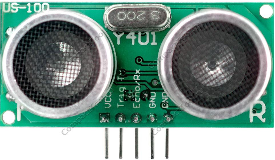
The US100 is a high-performance ultrasonic sensor designed for precise distance measurement and object detection. It operates by emitting ultrasonic waves and calculating the time taken for the echo to return, enabling accurate distance calculations. The US100 is versatile and can operate in both UART (serial) and PWM modes, making it suitable for a wide range of applications.
Explore Projects Built with US100
 Open Project in Cirkit Designer
 Open Project in Cirkit Designer
 Open Project in Cirkit Designer
 Open Project in Cirkit Designer
Explore Projects Built with US100
Open Project in Cirkit DesignerOpen Project in Cirkit DesignerOpen Project in Cirkit DesignerOpen Project in Cirkit DesignerCommon Applications
- Robotics for obstacle detection and avoidance
- Distance measurement in automation systems
- Liquid level sensing in tanks
- Proximity detection in security systems
- Smart parking systems
Technical Specifications
Below are the key technical details of the US100 ultrasonic sensor:
| Parameter | Value |
|---|---|
| Operating Voltage | 2.4V to 5.5V |
| Operating Current | ≤ 2mA |
| Measuring Range | 2cm to 450cm |
| Measuring Accuracy | ±0.3cm |
| Operating Modes | UART (serial) and PWM |
| Communication Protocol | UART: 9600 baud rate |
| Working Temperature | -20°C to 70°C |
| Dimensions | 45mm x 20mm x 15mm |
Pin Configuration
The US100 sensor has four pins, as described in the table below:
| Pin | Name | Description |
|---|---|---|
| 1 | VCC | Power supply pin (2.4V to 5.5V) |
| 2 | Trig/TX | Trigger pin for PWM mode / TX pin for UART mode |
| 3 | Echo/RX | Echo pin for PWM mode / RX pin for UART mode |
| 4 | GND | Ground connection |
Usage Instructions
The US100 can operate in two modes: UART (serial communication) and PWM (pulse width modulation). Below are instructions for using the sensor in each mode.
Using the US100 in UART Mode
- Connect the VCC pin to a 5V power supply and the GND pin to ground.
- Connect the Trig/TX pin to the TX pin of your microcontroller.
- Connect the Echo/RX pin to the RX pin of your microcontroller.
- Send a command via UART to initiate a measurement. The sensor will return the distance in millimeters.
Example Code for Arduino UNO (UART Mode)
#include <SoftwareSerial.h>

// Define RX and TX pins for SoftwareSerial
SoftwareSerial us100(10, 11); // RX = 10, TX = 11

void setup() {
  Serial.begin(9600);         // Initialize Serial Monitor
  us100.begin(9600);          // Initialize US100 communication
  Serial.println("US100 Sensor Initialized");
}

void loop() {
  us100.write(0x55);          // Send measurement command to US100
  delay(100);                 // Wait for the response

  if (us100.available() >= 2) { // Check if data is available
    int highByte = us100.read(); // Read high byte of distance
    int lowByte = us100.read();  // Read low byte of distance
    int distance = (highByte << 8) + lowByte; // Combine bytes into distance

    Serial.print("Distance: ");
    Serial.print(distance);
    Serial.println(" mm");
  }
  delay(500);                 // Wait before next measurement
}
Using the US100 in PWM Mode
- Connect the VCC pin to a 5V power supply and the GND pin to ground.
- Connect the Trig/TX pin to a digital output pin on your microcontroller.
- Connect the Echo/RX pin to a digital input pin on your microcontroller.
- Send a 10µs HIGH pulse to the Trig/TX pin to trigger the sensor.
- Measure the duration of the HIGH pulse on the Echo/RX pin to calculate the distance.
Example Code for Arduino UNO (PWM Mode)
#define TRIG_PIN 9  // Define Trig pin
#define ECHO_PIN 8  // Define Echo pin

void setup() {
  Serial.begin(9600);         // Initialize Serial Monitor
  pinMode(TRIG_PIN, OUTPUT);  // Set Trig pin as output
  pinMode(ECHO_PIN, INPUT);   // Set Echo pin as input
  Serial.println("US100 Sensor Initialized");
}

void loop() {
  digitalWrite(TRIG_PIN, LOW); // Ensure Trig pin is LOW
  delayMicroseconds(2);
  digitalWrite(TRIG_PIN, HIGH); // Send 10µs HIGH pulse
  delayMicroseconds(10);
  digitalWrite(TRIG_PIN, LOW);

  // Measure the duration of the HIGH pulse on Echo pin
  long duration = pulseIn(ECHO_PIN, HIGH);

  // Calculate distance in cm (duration / 58 = distance in cm)
  float distance = duration / 58.0;

  Serial.print("Distance: ");
  Serial.print(distance);
  Serial.println(" cm");

  delay(500);                 // Wait before next measurement
}
Important Considerations
- Ensure the sensor is powered within its operating voltage range (2.4V to 5.5V).
- Avoid placing the sensor near ultrasonic noise sources to prevent interference.
- For accurate measurements, ensure the sensor is perpendicular to the target surface.
- Use decoupling capacitors (e.g., 10µF and 0.1µF) across the power supply pins to reduce noise.
Troubleshooting and FAQs
Common Issues and Solutions
No response from the sensor in UART mode:
- Ensure the baud rate is set to 9600.
- Verify the TX and RX connections are correct.
- Check the power supply voltage (2.4V to 5.5V).
Incorrect distance readings in PWM mode:
- Ensure the Trig pin receives a 10µs HIGH pulse.
- Verify the Echo pin is connected to the correct input pin.
- Check for obstacles or reflective surfaces causing interference.
Unstable or fluctuating readings:
- Use a stable power supply with proper decoupling capacitors.
- Ensure there are no moving objects or noise sources near the sensor.
Sensor not working at all:
- Double-check all connections and ensure the sensor is not damaged.
- Test the sensor with a different microcontroller or power source.
FAQs
Q: Can the US100 measure distances below 2cm?
A: No, the minimum measurable distance is 2cm. Objects closer than this may not be detected accurately.
Q: What is the maximum range of the US100?
A: The US100 can measure distances up to 450cm under ideal conditions.
Q: Can the US100 operate in both UART and PWM modes simultaneously?
A: No, the sensor operates in either UART or PWM mode, depending on how it is connected.
Q: Is the US100 waterproof?
A: No, the US100 is not waterproof. For outdoor or wet environments, consider using a waterproof ultrasonic sensor.
Q: Can the US100 be used with a 3.3V microcontroller?
A: Yes, the US100 operates within a voltage range of 2.4V to 5.5V, making it compatible with 3.3V systems.