How to Use IMU: Examples, Pinouts, and Specs
Introduction
The GY-BNO085 is an advanced Inertial Measurement Unit (IMU) manufactured by Teyleten Robot. This IMU integrates accelerometers, gyroscopes, and magnetometers to provide precise measurements of specific force, angular rate, and magnetic field. It is widely used in applications requiring accurate motion tracking and orientation sensing.
Common applications include:
- Robotics for navigation and control
- Drones for stabilization and flight control
- Virtual reality (VR) and augmented reality (AR) systems
- Wearable devices for motion tracking
- Automotive systems for navigation and stability control
Explore Projects Built with IMU


Explore Projects Built with IMU
Technical Specifications
The GY-BNO085 is a high-performance IMU with the following key specifications:
| Parameter | Value |
|---|---|
| Manufacturer | Teyleten Robot |
| Part Number | GY-BNO085 |
| Operating Voltage | 3.3V - 5V |
| Communication Protocols | I2C, SPI |
| Accelerometer Range | ±2g, ±4g, ±8g, ±16g |
| Gyroscope Range | ±125°/s, ±250°/s, ±500°/s, ±1000°/s, ±2000°/s |
| Magnetometer Range | ±4900 µT |
| Operating Temperature | -40°C to +85°C |
| Dimensions | 15mm x 15mm |
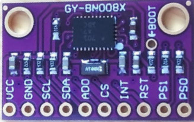
Pin Configuration and Descriptions
The GY-BNO085 has the following pinout:
| Pin | Name | Description |
|---|---|---|
| 1 | VIN | Power input (3.3V - 5V) |
| 2 | GND | Ground |
| 3 | SCL | I2C Clock Line (or SPI Clock in SPI mode) |
| 4 | SDA | I2C Data Line (or SPI MOSI in SPI mode) |
| 5 | CS | Chip Select (used in SPI mode; connect to GND for I2C mode) |
| 6 | INT | Interrupt pin (used for event notifications) |
| 7 | RST | Reset pin (optional, used to reset the module) |
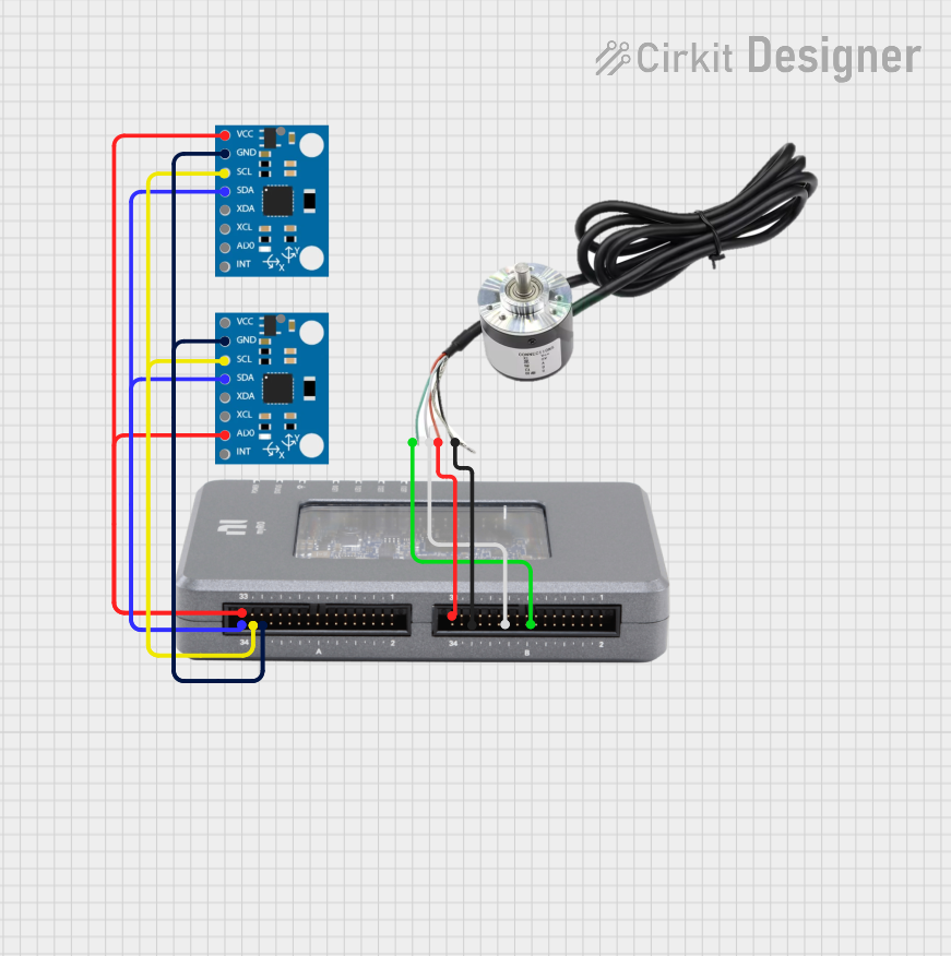
Usage Instructions
How to Use the GY-BNO085 in a Circuit
- Power the Module: Connect the VIN pin to a 3.3V or 5V power source and the GND pin to ground.
- Select Communication Protocol:
- For I2C: Connect the SCL and SDA pins to the corresponding I2C pins on your microcontroller. Ensure the CS pin is connected to GND.
- For SPI: Connect the SCL, SDA (MOSI), and CS pins to the corresponding SPI pins on your microcontroller.
- Pull-Up Resistors: If using I2C, ensure pull-up resistors (typically 4.7kΩ) are connected to the SCL and SDA lines.
- Interrupt Pin: Optionally, connect the INT pin to a GPIO pin on your microcontroller to handle interrupts.
- Reset Pin: Optionally, connect the RST pin to a GPIO pin for resetting the module.
Important Considerations and Best Practices
- Power Supply: Ensure a stable power supply to avoid measurement inaccuracies.
- I2C Address: The default I2C address of the GY-BNO085 is
0x4A. Verify this in your setup. - Orientation: Mount the IMU securely and in the correct orientation for accurate readings.
- Calibration: Perform sensor calibration (accelerometer, gyroscope, and magnetometer) for optimal performance.
- Noise Filtering: Use software filtering techniques to reduce noise in sensor data.
Example Code for Arduino UNO
Below is an example of how to interface the GY-BNO085 with an Arduino UNO using the I2C protocol:
#include <Wire.h> // Include the Wire library for I2C communication

#define BNO085_I2C_ADDRESS 0x4A // Default I2C address of the GY-BNO085

void setup() {
  Wire.begin(); // Initialize I2C communication
  Serial.begin(9600); // Start serial communication for debugging

  // Check if the IMU is connected
  Wire.beginTransmission(BNO085_I2C_ADDRESS);
  if (Wire.endTransmission() == 0) {
    Serial.println("GY-BNO085 connected successfully!");
  } else {
    Serial.println("Failed to connect to GY-BNO085. Check wiring.");
    while (1); // Halt execution if the IMU is not detected
  }
}

void loop() {
  // Example: Request data from the IMU
  Wire.beginTransmission(BNO085_I2C_ADDRESS);
  Wire.write(0x00); // Example register address (replace with actual register)
  Wire.endTransmission();

  Wire.requestFrom(BNO085_I2C_ADDRESS, 6); // Request 6 bytes of data
  if (Wire.available() == 6) {
    int16_t accelX = Wire.read() | (Wire.read() << 8); // Read X-axis acceleration
    int16_t accelY = Wire.read() | (Wire.read() << 8); // Read Y-axis acceleration
    int16_t accelZ = Wire.read() | (Wire.read() << 8); // Read Z-axis acceleration

    // Print the acceleration values
    Serial.print("Accel X: "); Serial.print(accelX);
    Serial.print(" Y: "); Serial.print(accelY);
    Serial.print(" Z: "); Serial.println(accelZ);
  }

  delay(100); // Delay for stability
}
Troubleshooting and FAQs
Common Issues
IMU Not Detected:
- Ensure the wiring is correct and the power supply is stable.
- Verify the I2C address (
0x4A) matches your setup. - Check for loose connections or damaged wires.
Inaccurate Readings:
- Perform sensor calibration to account for environmental factors.
- Ensure the IMU is mounted securely and not subject to vibrations.
Communication Errors:
- Verify pull-up resistors are present on the I2C lines.
- Check the microcontroller's I2C or SPI configuration.
Solutions and Tips for Troubleshooting
- Use a multimeter to verify power and ground connections.
- Test the I2C or SPI bus with a known working device to rule out microcontroller issues.
- Update the firmware or library for the GY-BNO085 if available.
- Consult the manufacturer's datasheet for advanced debugging techniques.
By following this documentation, you can effectively integrate the GY-BNO085 IMU into your projects and achieve accurate motion and orientation sensing.