
How to Use Microchip ATtiny85 (PDIP-8): Examples, Pinouts, and Specs

 Design with Microchip ATtiny85 (PDIP-8) in Cirkit Designer
Introduction
The Microchip ATtiny85 is a compact, low-power 8-bit microcontroller designed for embedded applications and simple control tasks. With its small form factor and versatile features, the ATtiny85 is ideal for projects requiring minimal space and power consumption. It features 8 KB of flash memory, 512 bytes of SRAM, and 6 general-purpose I/O pins, making it a popular choice for hobbyists and professionals alike.
Explore Projects Built with Microchip ATtiny85 (PDIP-8)
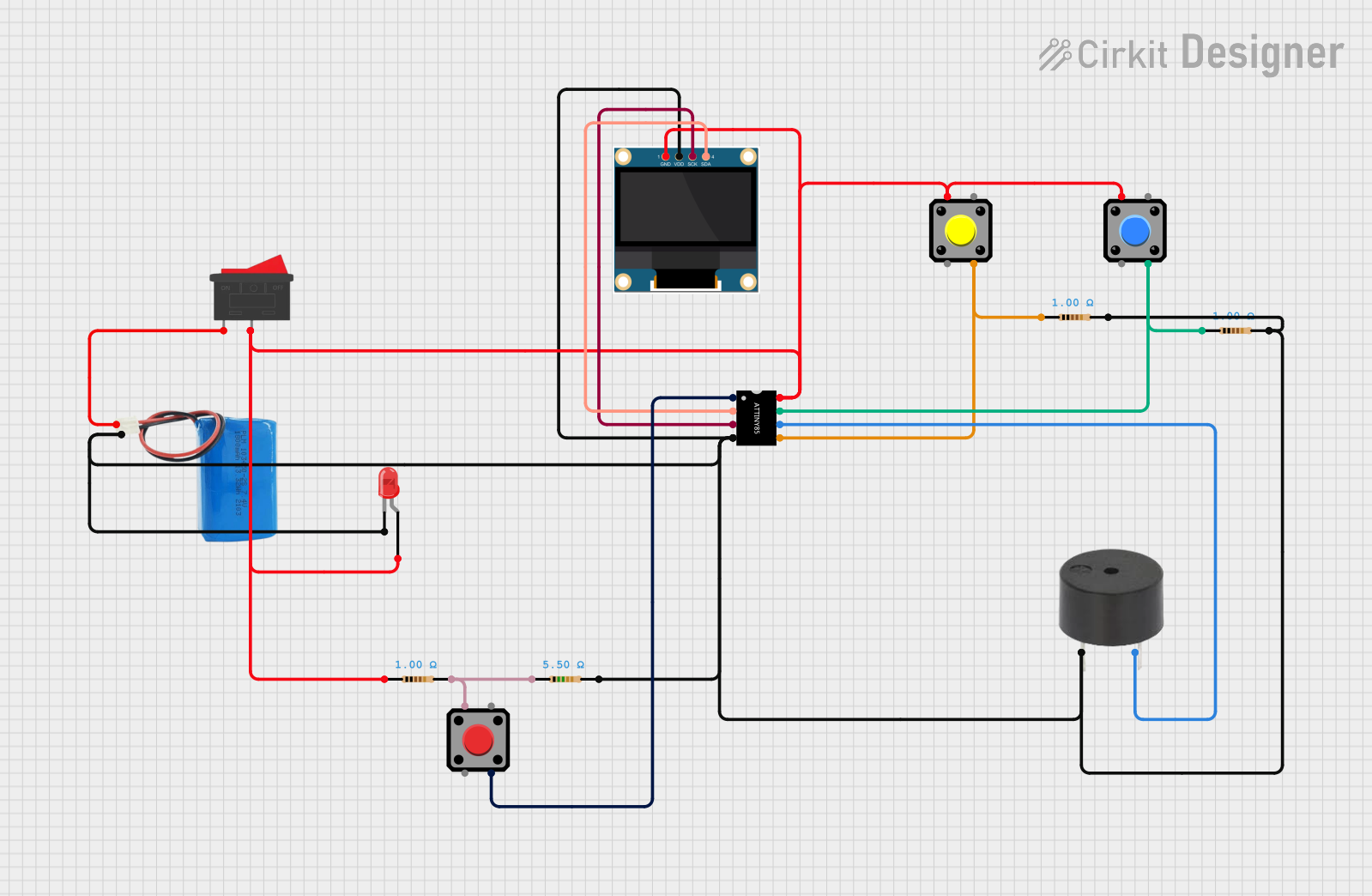 Open Project in Cirkit Designer
 Open Project in Cirkit Designer
 Open Project in Cirkit Designer
 Open Project in Cirkit Designer
Explore Projects Built with Microchip ATtiny85 (PDIP-8)
Open Project in Cirkit DesignerOpen Project in Cirkit DesignerOpen Project in Cirkit DesignerOpen Project in Cirkit DesignerCommon Applications and Use Cases
- Wearable electronics
- IoT devices and sensors
- LED control and lighting systems
- Small robotics and automation
- Battery-powered devices
- Simple data logging systems
Technical Specifications
The ATtiny85 is packed with features that make it suitable for a wide range of applications. Below are its key technical specifications:
| Parameter | Value |
|---|---|
| Manufacturer | Microchip Technology |
| Part Number | ATtiny85 |
| Architecture | 8-bit AVR |
| Flash Memory | 8 KB |
| SRAM | 512 bytes |
| EEPROM | 512 bytes |
| Operating Voltage | 2.7V to 5.5V |
| Clock Speed | Up to 20 MHz (with external clock) |
| I/O Pins | 6 |
| ADC Channels | 4 (10-bit resolution) |
| PWM Channels | 2 |
| Communication Interfaces | I2C, SPI, and UART (via software) |
| Package Type | PDIP-8 |
| Power Consumption | Low-power modes available |
Pin Configuration and Descriptions
The ATtiny85 comes in an 8-pin PDIP package. Below is the pinout and description:
| Pin Number | Pin Name | Description |
|---|---|---|
| 1 | PB5 (RESET) | Reset pin (active low) / GPIO / ADC input |
| 2 | PB3 | GPIO / ADC input / PWM output / SPI MOSI |
| 3 | PB4 | GPIO / ADC input / PWM output / SPI MISO |
| 4 | GND | Ground |
| 5 | PB0 | GPIO / ADC input / PWM output / SPI SCK |
| 6 | PB1 | GPIO / ADC input / PWM output |
| 7 | PB2 | GPIO / ADC input / I2C SDA / SPI SS |
| 8 | VCC | Power supply (2.7V to 5.5V) |
Usage Instructions
The ATtiny85 is versatile and can be used in a variety of circuits. Below are the steps and considerations for using it effectively:
Basic Circuit Setup
- Power Supply: Connect the VCC pin (Pin 8) to a 2.7V–5.5V power source and the GND pin (Pin 4) to ground.
- Reset Pin: If not used, connect the RESET pin (Pin 1) to VCC through a 10 kΩ pull-up resistor.
- I/O Pins: Use PB0–PB5 (Pins 2, 3, 5, 6, 7) as general-purpose I/O or for specific functions like ADC, PWM, or communication.
- Clock Source: The ATtiny85 has an internal 8 MHz oscillator. For higher speeds, an external clock can be connected to PB4 (Pin 3).
Programming the ATtiny85
The ATtiny85 can be programmed using an Arduino UNO as an ISP (In-System Programmer). Follow these steps:
- Connect the Arduino UNO to the ATtiny85 as follows:
- Arduino Pin 10 → ATtiny85 Pin 1 (RESET)
- Arduino Pin 11 → ATtiny85 Pin 5 (MOSI)
- Arduino Pin 12 → ATtiny85 Pin 6 (MISO)
- Arduino Pin 13 → ATtiny85 Pin 7 (SCK)
- Arduino GND → ATtiny85 Pin 4 (GND)
- Arduino 5V → ATtiny85 Pin 8 (VCC)
- Load the "ArduinoISP" sketch onto the Arduino UNO.
- Use the Arduino IDE to upload your program to the ATtiny85. Select the appropriate board and programmer settings.
Example Code
Below is an example of using the ATtiny85 to blink an LED connected to PB0 (Pin 5):
// Blink an LED on PB0 (Pin 5) of the ATtiny85
// Ensure the LED is connected with a current-limiting resistor

#define LED_PIN 0  // PB0 is digital pin 0 on the ATtiny85

void setup() {
  pinMode(LED_PIN, OUTPUT);  // Set PB0 as an output pin
}

void loop() {
  digitalWrite(LED_PIN, HIGH);  // Turn the LED on
  delay(1000);                  // Wait for 1 second
  digitalWrite(LED_PIN, LOW);   // Turn the LED off
  delay(1000);                  // Wait for 1 second
}
Important Considerations
- Power Supply: Ensure the voltage is within the operating range (2.7V–5.5V).
- Pull-Up Resistors: Use pull-up resistors on the RESET pin if not used.
- Decoupling Capacitor: Place a 0.1 µF capacitor between VCC and GND for noise reduction.
- Programming: Use a reliable ISP programmer or Arduino UNO for uploading code.
Troubleshooting and FAQs
Common Issues
The ATtiny85 is not responding to programming commands.
- Ensure the wiring between the programmer and the ATtiny85 is correct.
- Verify that the ArduinoISP sketch is loaded on the Arduino UNO.
- Check the power supply voltage and connections.
The LED does not blink in the example code.
- Confirm the LED and resistor are connected to the correct pin (PB0).
- Check for loose connections or incorrect resistor values.
The ATtiny85 overheats during operation.
- Verify that the supply voltage does not exceed 5.5V.
- Ensure no I/O pins are shorted to ground or VCC.
FAQs
Q: Can the ATtiny85 run on batteries?
A: Yes, the ATtiny85 is designed for low-power applications and can run on batteries. Use sleep modes to extend battery life.
Q: How do I use the ATtiny85 for I2C communication?
A: The ATtiny85 supports I2C via software libraries like TinyWire. Connect PB0 (SCL) and PB2 (SDA) to the I2C bus.
Q: Can I use the ATtiny85 without an external clock?
A: Yes, the ATtiny85 has an internal 8 MHz oscillator, which is sufficient for most applications.
By following this documentation, you can effectively integrate the Microchip ATtiny85 into your projects and troubleshoot common issues with ease.