
How to Use ATTINY24: Examples, Pinouts, and Specs
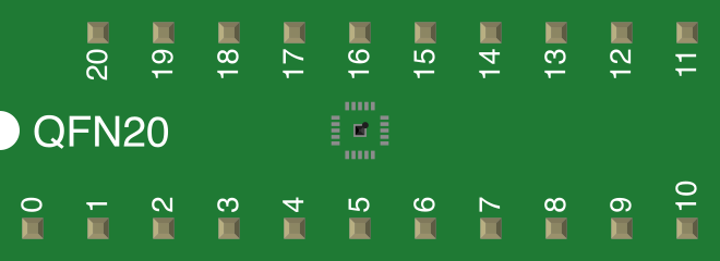
 Design with ATTINY24 in Cirkit Designer
Introduction
The ATTINY24 is a low-power 8-bit microcontroller from Atmel's AVR family, designed for small embedded applications. It features 2KB of flash memory, 128 bytes of SRAM, and 16 general-purpose I/O pins. This microcontroller is ideal for projects requiring compact size, low power consumption, and versatile functionality. It supports various communication protocols, including SPI and I²C, making it suitable for a wide range of applications.
Explore Projects Built with ATTINY24
 Open Project in Cirkit Designer
 Open Project in Cirkit Designer
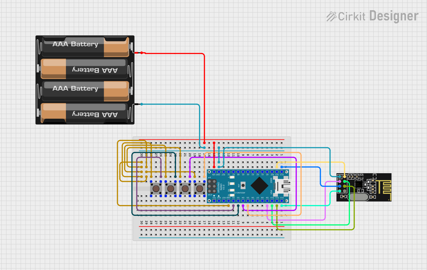 Open Project in Cirkit Designer
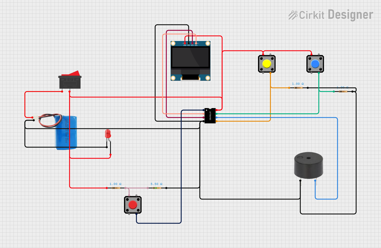 Open Project in Cirkit Designer
Explore Projects Built with ATTINY24
Open Project in Cirkit DesignerOpen Project in Cirkit DesignerOpen Project in Cirkit DesignerOpen Project in Cirkit DesignerCommon Applications
- Home automation systems
- Sensor interfacing and data logging
- Wearable devices
- Small robotics and motor control
- Low-power IoT devices
Technical Specifications
Key Technical Details
| Parameter | Value |
|---|---|
| Architecture | 8-bit AVR |
| Flash Memory | 2KB |
| SRAM | 128 bytes |
| EEPROM | 128 bytes |
| Operating Voltage | 1.8V to 5.5V |
| Clock Speed | Up to 20 MHz (with external crystal) |
| I/O Pins | 16 general-purpose pins |
| Communication Interfaces | SPI, I²C (TWI), USART |
| Timers | Two 8-bit timers, one 16-bit timer |
| ADC | 10-bit ADC with up to 8 channels |
| Power Consumption | <1 µA in power-down mode |
Pin Configuration and Descriptions
The ATTINY24 is available in a 14-pin PDIP/SOIC package. Below is the pinout and description:
| Pin Number | Pin Name | Description |
|---|---|---|
| 1 | VCC | Power supply (1.8V to 5.5V) |
| 2 | PB0 | General-purpose I/O, ADC0, PCINT0 |
| 3 | PB1 | General-purpose I/O, ADC1, PCINT1 |
| 4 | PB3 | General-purpose I/O, ADC3, PCINT3 |
| 5 | PB2 | General-purpose I/O, ADC2, PCINT2 |
| 6 | PA7 | General-purpose I/O, ADC7, PCINT7 |
| 7 | PA6 | General-purpose I/O, ADC6, PCINT6 |
| 8 | PA5 | General-purpose I/O, ADC5, PCINT5 |
| 9 | PA4 | General-purpose I/O, ADC4, PCINT4 |
| 10 | PA3 | General-purpose I/O, ADC3, PCINT3 |
| 11 | PA2 | General-purpose I/O, ADC2, PCINT2 |
| 12 | PA1 | General-purpose I/O, ADC1, PCINT1 |
| 13 | PA0 | General-purpose I/O, ADC0, PCINT0 |
| 14 | GND | Ground |
Usage Instructions
How to Use the ATTINY24 in a Circuit
- Power Supply: Connect the VCC pin to a regulated power source (1.8V to 5.5V) and the GND pin to ground.
- Clock Source: Use the internal 8 MHz oscillator or connect an external crystal oscillator to the XTAL1 and XTAL2 pins for higher precision.
- Programming: Use an ISP (In-System Programmer) to upload code to the ATTINY24. Popular tools include the Atmel AVRISP or USBasp.
- I/O Configuration: Configure the I/O pins as input or output in the code. Use pull-up resistors for input pins if needed.
- Communication: Utilize the SPI or I²C interface for communication with other devices.
Example: Blinking an LED with ATTINY24
Below is an example of how to blink an LED connected to pin PA0 of the ATTINY24. This code can be written in AVR C and uploaded using an ISP programmer.
#include <avr/io.h>
#include <util/delay.h>

#define LED_PIN PA0  // Define the LED pin as PA0

int main(void) {
    DDRA |= (1 << LED_PIN);  // Set PA0 as an output pin

    while (1) {
        PORTA |= (1 << LED_PIN);  // Turn the LED on
        _delay_ms(500);          // Wait for 500 milliseconds

        PORTA &= ~(1 << LED_PIN); // Turn the LED off
        _delay_ms(500);          // Wait for 500 milliseconds
    }

    return 0;
}
Important Considerations
- Power Consumption: Use sleep modes to minimize power consumption in battery-powered applications.
- Decoupling Capacitors: Place a 0.1 µF capacitor between VCC and GND to stabilize the power supply.
- Programming Voltage: Ensure the programming voltage matches the operating voltage of the ATTINY24.
Troubleshooting and FAQs
Common Issues
Microcontroller Not Responding
- Cause: Incorrect power supply or missing decoupling capacitor.
- Solution: Verify the power supply voltage and add a 0.1 µF capacitor between VCC and GND.
Code Upload Fails
- Cause: Incorrect ISP connections or fuse settings.
- Solution: Double-check the ISP wiring and ensure the correct fuse bits are set for the desired clock source.
I/O Pins Not Working
- Cause: Pins not configured correctly in the code.
- Solution: Ensure the pins are set as input or output in the DDRx register.
High Power Consumption
- Cause: Sleep modes not enabled or unused peripherals active.
- Solution: Enable sleep modes and disable unused peripherals in the code.
FAQs
Q: Can the ATTINY24 run without an external crystal?
A: Yes, the ATTINY24 has an internal 8 MHz oscillator that can be used as the clock source.
Q: How do I reset the ATTINY24?
A: The ATTINY24 can be reset by pulling the RESET pin low or by using a watchdog timer reset.
Q: Can I use the ATTINY24 with Arduino IDE?
A: Yes, with the appropriate core files (e.g., ATTinyCore), the ATTINY24 can be programmed using the Arduino IDE.
Q: What is the maximum current per I/O pin?
A: Each I/O pin can source or sink up to 20 mA, but the total current for all pins should not exceed 200 mA.