How to Use RFID522: Examples, Pinouts, and Specs
Introduction
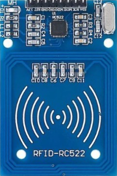
The RFID522 is a low-cost RFID reader/writer module that operates at a frequency of 13.56 MHz. It is widely used for reading and writing RFID tags and cards, making it an essential component in various applications such as access control, inventory management, and identification systems. Its compact design, low power consumption, and compatibility with microcontrollers like Arduino make it a popular choice for hobbyists and professionals alike.
Explore Projects Built with RFID522

Explore Projects Built with RFID522
Common Applications:
- Access control systems (e.g., door locks, attendance systems)
- Inventory and asset tracking
- Contactless payment systems
- Identification and authentication systems
- DIY electronics projects involving RFID technology
Technical Specifications
Below are the key technical details of the RFID522 module:
| Parameter | Specification |
|---|---|
| Operating Frequency | 13.56 MHz |
| Operating Voltage | 2.5V to 3.3V |
| Communication Interface | SPI, I2C, UART |
| Maximum Data Rate | 10 Mbps |
| Current Consumption | 13-26 mA (active mode) |
| Supported Protocols | ISO/IEC 14443A |
| Reading Distance | Up to 5 cm (depending on tag type) |
| Dimensions | 40 mm x 60 mm |
Pin Configuration and Descriptions
The RFID522 module typically has an 8-pin interface for communication and power. Below is the pinout description:
| Pin | Name | Description |
|---|---|---|
| 1 | VCC | Power supply input (3.3V recommended) |
| 2 | RST | Reset pin. Active LOW. Used to reset the module. |
| 3 | GND | Ground connection |
| 4 | IRQ | Interrupt pin. Can be used to signal events (optional, not always required). |
| 5 | MISO | SPI Master-In-Slave-Out (data output from RFID522 to microcontroller) |
| 6 | MOSI | SPI Master-Out-Slave-In (data input from microcontroller to RFID522) |
| 7 | SCK | SPI Clock signal |
| 8 | SDA/SS | SPI Slave Select (chip select) or I2C data line (depending on configuration) |
Usage Instructions
Connecting the RFID522 to an Arduino UNO
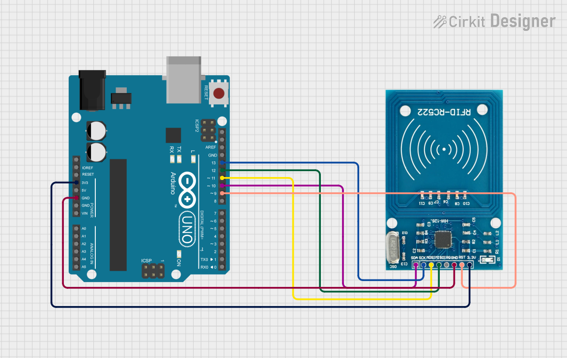
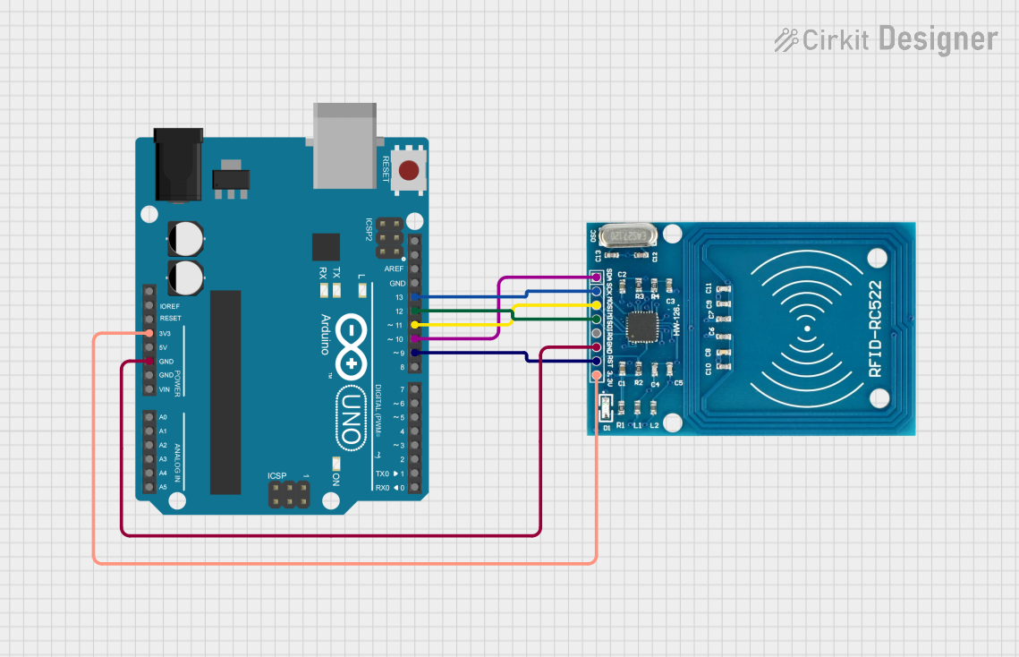
The RFID522 module can be easily interfaced with an Arduino UNO using the SPI communication protocol. Below is the wiring guide:
| RFID522 Pin | Arduino UNO Pin |
|---|---|
| VCC | 3.3V |
| GND | GND |
| RST | Pin 9 |
| IRQ | Not connected |
| MISO | Pin 12 |
| MOSI | Pin 11 |
| SCK | Pin 13 |
| SDA/SS | Pin 10 |
Sample Arduino Code
The following example demonstrates how to use the RFID522 module with an Arduino UNO to read RFID tags. This code uses the popular MFRC522 library, which can be installed via the Arduino IDE Library Manager.
#include <SPI.h>
#include <MFRC522.h>

// Define RFID522 pins
#define RST_PIN 9  // Reset pin connected to Arduino pin 9
#define SS_PIN 10  // Slave Select pin connected to Arduino pin 10

MFRC522 rfid(SS_PIN, RST_PIN); // Create an instance of the MFRC522 class

void setup() {
  Serial.begin(9600); // Initialize serial communication
  SPI.begin();        // Initialize SPI bus
  rfid.PCD_Init();    // Initialize the RFID module
  Serial.println("Place your RFID tag near the reader...");
}

void loop() {
  // Check if a new RFID card is present
  if (!rfid.PICC_IsNewCardPresent()) {
    return; // Exit if no card is detected
  }

  // Check if the card can be read
  if (!rfid.PICC_ReadCardSerial()) {
    return; // Exit if the card cannot be read
  }

  // Print the UID (Unique Identifier) of the card
  Serial.print("Card UID: ");
  for (byte i = 0; i < rfid.uid.size; i++) {
    Serial.print(rfid.uid.uidByte[i], HEX); // Print each byte in hexadecimal
    Serial.print(" ");
  }
  Serial.println();

  // Halt the card to stop further communication
  rfid.PICC_HaltA();
}
Important Considerations:
- Power Supply: Ensure the module is powered with 3.3V. Supplying 5V may damage the module.
- Tag Distance: The reading distance depends on the type of RFID tag used. Ensure the tag is within 5 cm of the module.
- Library Installation: Install the
MFRC522library in the Arduino IDE before uploading the code. - SPI Configuration: Ensure the SPI pins on the Arduino are correctly connected to the RFID522 module.
Troubleshooting and FAQs
Common Issues and Solutions
Module Not Responding:
- Ensure the wiring is correct and matches the pinout table.
- Verify that the module is powered with 3.3V (not 5V).
- Check the connections for loose wires or poor soldering.
Card Not Detected:
- Ensure the card is within the 5 cm range of the module.
- Verify that the card/tag is compatible with the ISO/IEC 14443A standard.
Error in Serial Monitor:
- Ensure the
MFRC522library is installed and included in the code. - Check the baud rate in the Serial Monitor (should match
Serial.begin(9600)).
- Ensure the
Interference Issues:
- Avoid placing the module near metal objects or other electronic devices that may cause interference.
FAQs
Q1: Can the RFID522 module write data to RFID tags?
Yes, the RFID522 module supports both reading and writing operations for compatible RFID tags.
Q2: Can I use the RFID522 with a 5V microcontroller?
Yes, but you must use a logic level shifter to convert the 5V signals to 3.3V to avoid damaging the module.
Q3: What is the maximum range of the RFID522 module?
The maximum range is approximately 5 cm, depending on the type and size of the RFID tag.
Q4: Can I connect multiple RFID522 modules to a single Arduino?
Yes, you can connect multiple modules by assigning different Slave Select (SS) pins for each module.
By following this documentation, you should be able to successfully integrate and use the RFID522 module in your projects!