
How to Use Single-Chip USB to UART Bridge: Examples, Pinouts, and Specs
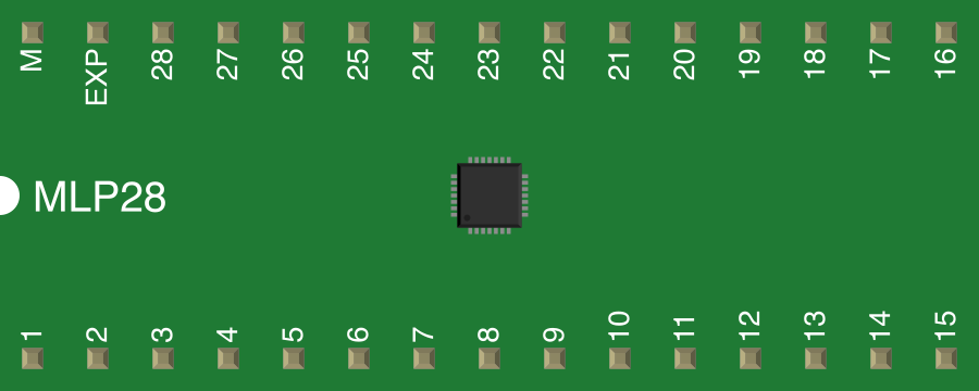
 Design with Single-Chip USB to UART Bridge in Cirkit Designer
Introduction
The Single-Chip USB to UART Bridge is a compact integrated circuit designed to enable seamless communication between USB devices and UART (Universal Asynchronous Receiver-Transmitter) interfaces. This component acts as a bridge, facilitating data transfer between microcontrollers and USB peripherals. It is widely used in embedded systems, prototyping, and debugging applications where USB connectivity is required.
Explore Projects Built with Single-Chip USB to UART Bridge
 Open Project in Cirkit Designer
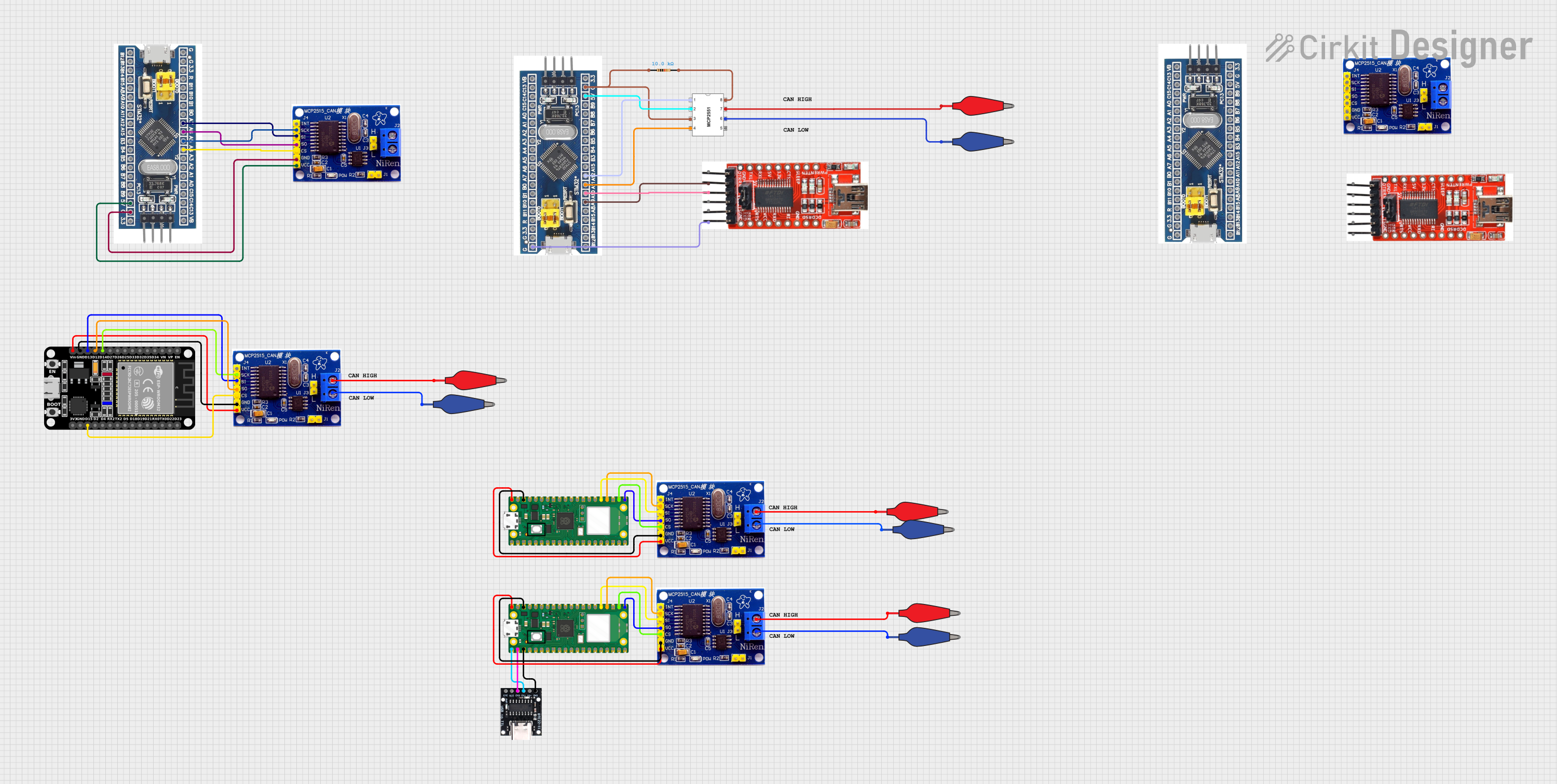 Open Project in Cirkit Designer
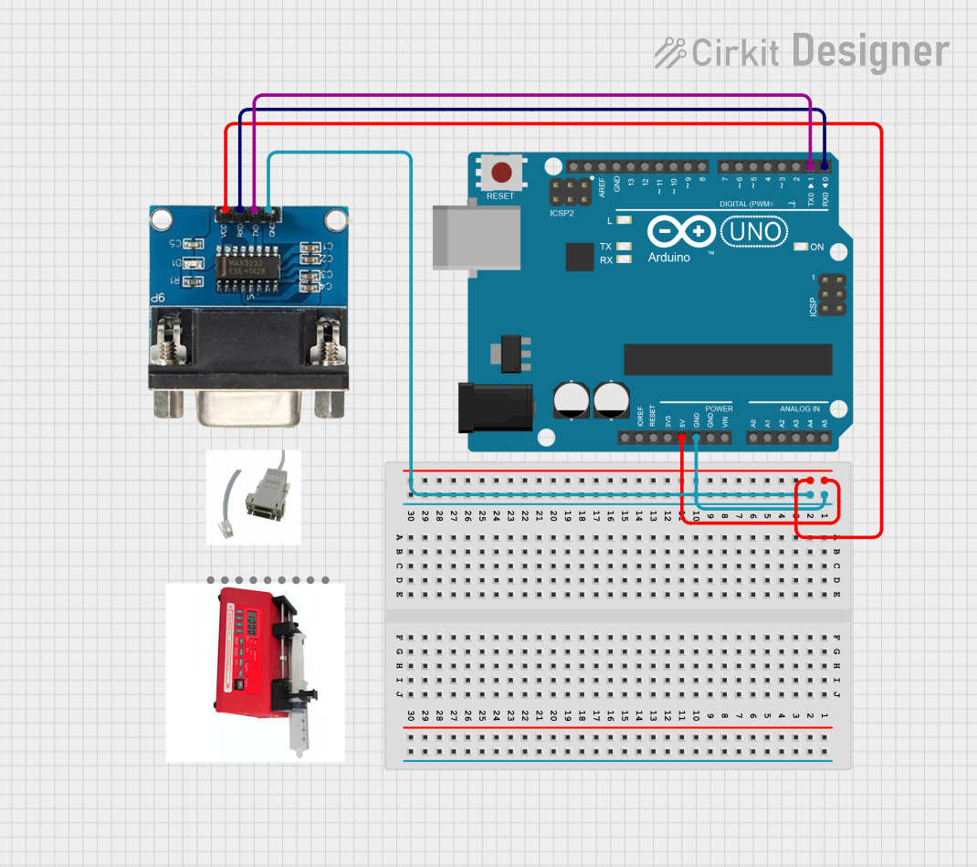 Open Project in Cirkit Designer
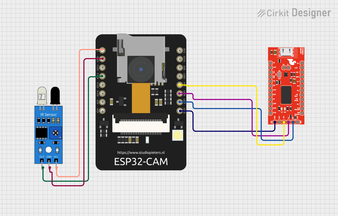 Open Project in Cirkit Designer
Explore Projects Built with Single-Chip USB to UART Bridge
Open Project in Cirkit DesignerOpen Project in Cirkit DesignerOpen Project in Cirkit DesignerOpen Project in Cirkit DesignerCommon Applications and Use Cases
- USB-to-serial communication for microcontrollers
- Debugging and programming embedded systems
- USB-based data logging and monitoring
- Connecting legacy UART devices to modern USB interfaces
- Prototyping USB-enabled projects
Technical Specifications
Below are the key technical details of the Single-Chip USB to UART Bridge:
| Parameter | Value |
|---|---|
| Supply Voltage (Vcc) | 3.3V or 5V |
| Operating Current | Typically 15-25 mA |
| USB Interface | USB 2.0 Full-Speed |
| UART Baud Rate | Up to 3 Mbps |
| Data Bits | 7 or 8 |
| Stop Bits | 1 or 2 |
| Parity | None, Even, Odd |
| Operating Temperature | -40°C to +85°C |
| Package Type | QFN, SSOP, or DIP |
Pin Configuration and Descriptions
The pinout of the Single-Chip USB to UART Bridge may vary slightly depending on the manufacturer, but a typical configuration is as follows:
| Pin Number | Pin Name | Description |
|---|---|---|
| 1 | VCC | Power supply input (3.3V or 5V). |
| 2 | GND | Ground connection. |
| 3 | TXD | UART Transmit Data. Sends data from the chip to the connected UART device. |
| 4 | RXD | UART Receive Data. Receives data from the connected UART device. |
| 5 | RTS# | Request to Send (active low). Optional UART flow control signal. |
| 6 | CTS# | Clear to Send (active low). Optional UART flow control signal. |
| 7 | DTR# | Data Terminal Ready (active low). Optional UART control signal. |
| 8 | DSR# | Data Set Ready (active low). Optional UART control signal. |
| 9 | USB_D+ | USB data line (positive). |
| 10 | USB_D- | USB data line (negative). |
| 11 | RESET# | Active low reset input. |
| 12 | NC | No connection (varies by manufacturer). |
Usage Instructions
How to Use the Component in a Circuit
- Power Supply: Connect the VCC pin to a 3.3V or 5V power source, depending on the chip's specifications. Connect the GND pin to the ground of your circuit.
- USB Connection: Connect the USB_D+ and USB_D- pins to the corresponding data lines of a USB connector. Ensure proper impedance matching for reliable communication.
- UART Connection: Connect the TXD and RXD pins to the UART device's RX and TX pins, respectively. If flow control is required, connect the RTS# and CTS# pins as well.
- Optional Reset: Use the RESET# pin to reset the chip if needed.
- Driver Installation: Install the appropriate USB-to-UART driver on your computer to enable communication with the chip.
Important Considerations and Best Practices
- Voltage Levels: Ensure that the UART device operates at the same voltage level as the chip (3.3V or 5V).
- Driver Compatibility: Verify that the USB-to-UART driver is compatible with your operating system.
- Signal Integrity: Use short and properly routed traces for USB and UART signals to minimize noise and interference.
- Flow Control: If using hardware flow control, ensure that the RTS# and CTS# pins are properly connected and configured.
Example: Connecting to an Arduino UNO
The Single-Chip USB to UART Bridge can be used to communicate between a computer and an Arduino UNO. Below is an example of Arduino code to send and receive data via UART:
// Example: Sending and receiving data via UART using Arduino UNO

void setup() {
  Serial.begin(9600); // Initialize UART communication at 9600 baud rate
  Serial.println("UART Bridge Example"); // Send a message to the computer
}

void loop() {
  if (Serial.available() > 0) {
    // Check if data is available to read from the computer
    char receivedChar = Serial.read(); // Read the incoming character
    Serial.print("Received: ");
    Serial.println(receivedChar); // Echo the received character back
  }
  delay(100); // Small delay to avoid overwhelming the UART buffer
}
Troubleshooting and FAQs
Common Issues and Solutions
No Communication Between USB and UART
- Cause: Incorrect driver installation or missing driver.
- Solution: Ensure the correct USB-to-UART driver is installed on your computer. Check the manufacturer's website for the latest driver.
Data Corruption or Loss
- Cause: Mismatched baud rate or improper signal connections.
- Solution: Verify that the baud rate of the UART device matches the configuration of the USB-to-UART bridge. Check all connections for proper wiring.
Device Not Recognized by Computer
- Cause: Faulty USB cable or incorrect wiring.
- Solution: Test with a different USB cable. Double-check the USB_D+ and USB_D- connections.
Flow Control Not Working
- Cause: RTS# and CTS# pins not connected or improperly configured.
- Solution: Ensure that hardware flow control is enabled in the software and that the RTS# and CTS# pins are correctly wired.
FAQs
Q: Can this chip be used with 1.8V UART devices?
A: Most Single-Chip USB to UART Bridges are designed for 3.3V or 5V operation. If you need to interface with a 1.8V device, use a level shifter.
Q: Is it possible to use this chip without flow control?
A: Yes, flow control is optional. You can leave the RTS# and CTS# pins unconnected if your application does not require it.
Q: How do I check if the driver is installed correctly?
A: On Windows, open the Device Manager and look for the USB-to-UART device under "Ports (COM & LPT)." On Linux, use the lsusb command to verify the device is detected.
Q: Can this chip support custom USB descriptors?
A: Some variants of the Single-Chip USB to UART Bridge allow customization of USB descriptors. Refer to the manufacturer's datasheet for details.