
How to Use ESP32-S3 GPIO Extension Board: Examples, Pinouts, and Specs
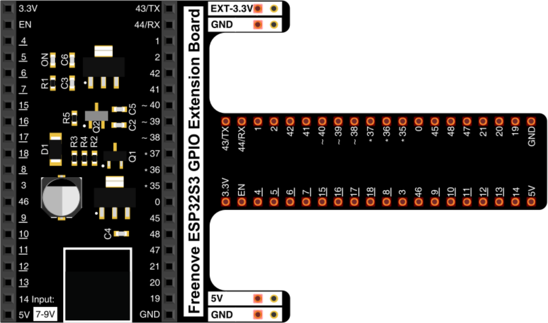
 Design with ESP32-S3 GPIO Extension Board in Cirkit Designer
Introduction
The ESP32-S3 GPIO Extension Board by Freenove is a versatile add-on designed to expand the GPIO capabilities of the ESP32-S3 microcontroller. This board provides additional GPIO pins, making it easier to interface with multiple sensors, actuators, and other peripherals simultaneously. It is ideal for projects requiring enhanced connectivity and functionality, such as IoT applications, robotics, and home automation systems.
Explore Projects Built with ESP32-S3 GPIO Extension Board
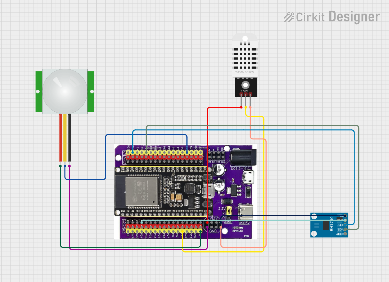 Open Project in Cirkit Designer
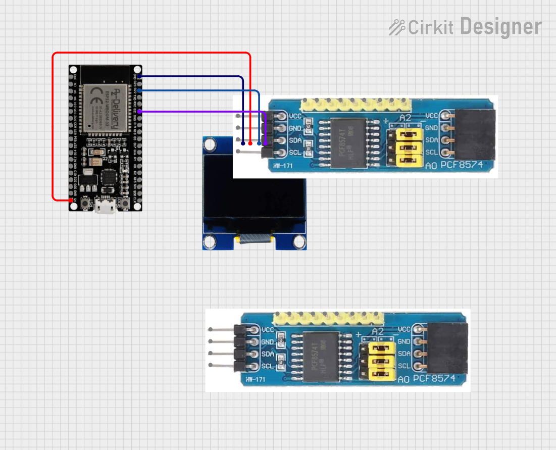 Open Project in Cirkit Designer
 Open Project in Cirkit Designer
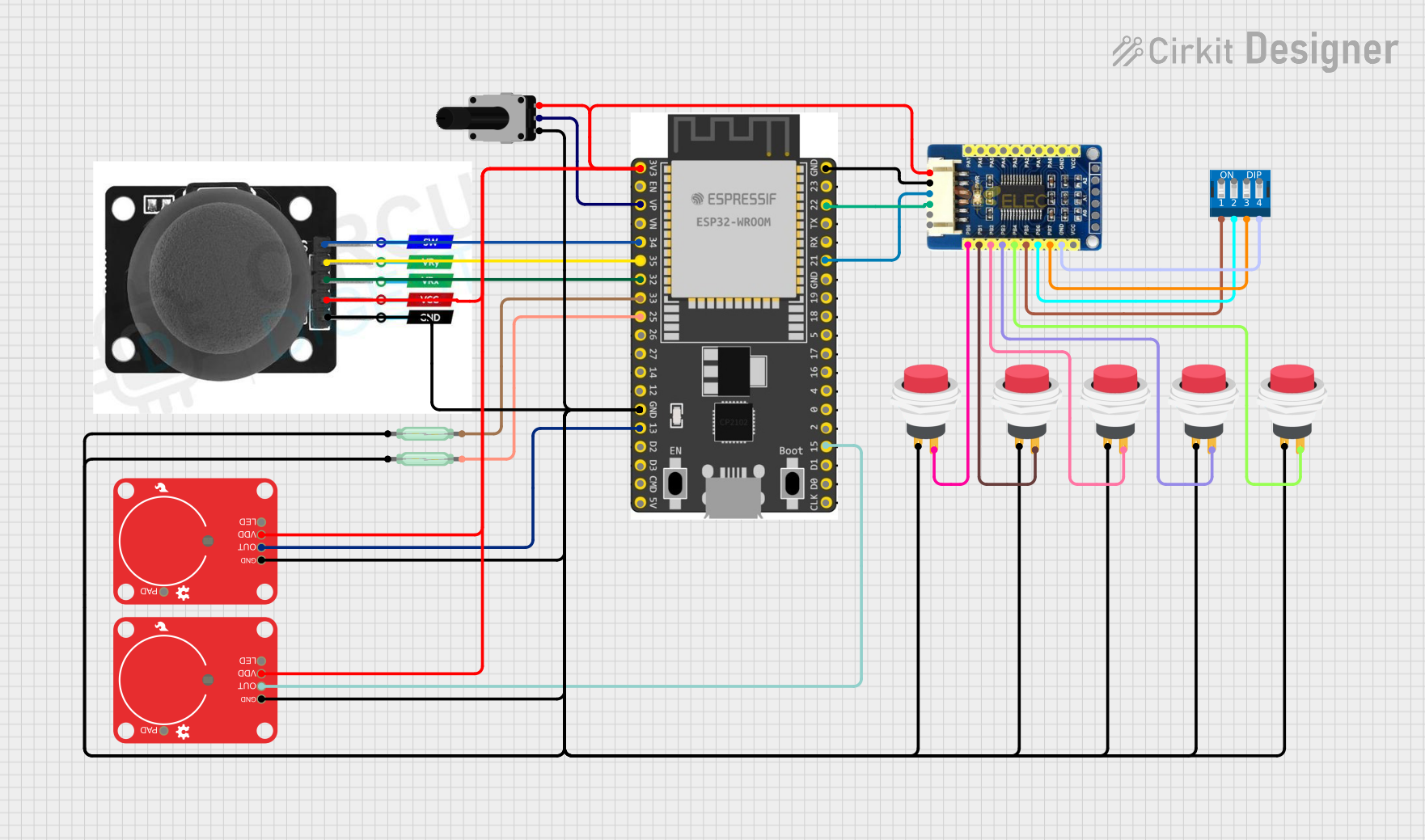 Open Project in Cirkit Designer
Explore Projects Built with ESP32-S3 GPIO Extension Board
Open Project in Cirkit DesignerOpen Project in Cirkit DesignerOpen Project in Cirkit DesignerOpen Project in Cirkit DesignerCommon Applications and Use Cases
- Expanding GPIO availability for complex projects
- Interfacing with multiple sensors and actuators
- Prototyping IoT devices with diverse hardware requirements
- Robotics projects requiring numerous input/output connections
- Educational purposes for learning microcontroller interfacing
Technical Specifications
The following table outlines the key technical details of the ESP32-S3 GPIO Extension Board:
| Specification | Details |
|---|---|
| Microcontroller | Compatible with ESP32-S3 |
| Operating Voltage | 3.3V |
| GPIO Pin Count | Up to 16 additional GPIO pins |
| Communication Protocol | I2C (for onboard GPIO expander) |
| Power Supply | 5V input via USB or external power source |
| Dimensions | 60mm x 40mm x 15mm |
| Connector Type | Pin headers and screw terminals |
Pin Configuration and Descriptions
The GPIO extension board uses an onboard GPIO expander IC (e.g., PCA9555 or similar) to provide additional GPIO pins. Below is the pin configuration:
| Pin Name | Description |
|---|---|
| GND | Ground connection |
| VCC | 3.3V power supply input |
| SDA | I2C data line (connect to ESP32-S3 SDA) |
| SCL | I2C clock line (connect to ESP32-S3 SCL) |
| GPIO0-GPIO15 | General-purpose input/output pins |
Usage Instructions
How to Use the Component in a Circuit
- Power the Board: Connect the VCC pin to a 3.3V power source and GND to ground.
- Connect I2C Lines: Link the SDA and SCL pins of the extension board to the corresponding SDA and SCL pins on the ESP32-S3.
- Access GPIO Pins: Use the GPIO0-GPIO15 pins to connect sensors, actuators, or other peripherals.
- Install Required Libraries: If using an I2C GPIO expander IC, install the appropriate library (e.g.,
Adafruit_PCA9555for PCA9555) in your development environment.
Important Considerations and Best Practices
- Ensure the ESP32-S3 and the GPIO extension board share a common ground.
- Avoid exceeding the current rating of the GPIO pins (typically 25mA per pin).
- Use pull-up resistors for the I2C lines if not already included on the board.
- Verify the I2C address of the GPIO expander IC (default is often
0x20but may vary).
Example Code for Arduino UNO-Compatible IDE
Below is an example code snippet to interface the ESP32-S3 GPIO Extension Board using the Adafruit_PCA9555 library:
#include <Wire.h>
#include <Adafruit_PCA9555.h>

// Create an instance of the PCA9555 class
Adafruit_PCA9555 gpioExpander;

void setup() {
  Serial.begin(115200); // Initialize serial communication for debugging
  Wire.begin();         // Initialize I2C communication

  // Initialize the GPIO expander with its I2C address (default: 0x20)
  if (!gpioExpander.begin(0x20)) {
    Serial.println("Failed to initialize GPIO expander!");
    while (1); // Halt execution if initialization fails
  }

  Serial.println("GPIO expander initialized successfully!");

  // Set GPIO0 as an output pin
  gpioExpander.pinMode(0, OUTPUT);
}

void loop() {
  // Toggle GPIO0 on and off
  gpioExpander.digitalWrite(0, HIGH); // Set GPIO0 to HIGH
  delay(1000);                        // Wait for 1 second
  gpioExpander.digitalWrite(0, LOW);  // Set GPIO0 to LOW
  delay(1000);                        // Wait for 1 second
}
Troubleshooting and FAQs
Common Issues Users Might Face
I2C Communication Failure:
- Cause: Incorrect wiring or I2C address mismatch.
- Solution: Double-check the SDA and SCL connections and verify the I2C address of the GPIO expander IC.
GPIO Pins Not Responding:
- Cause: Incorrect pin configuration or insufficient power supply.
- Solution: Ensure the pins are correctly configured as input or output and verify the power supply voltage.
Overheating or Damage:
- Cause: Exceeding the current rating of GPIO pins.
- Solution: Limit the current draw to within the safe range (typically 25mA per pin).
Solutions and Tips for Troubleshooting
- Use a multimeter to check voltage levels on the VCC and GND pins.
- Use an I2C scanner sketch to detect the GPIO expander's address.
- Ensure the ESP32-S3 firmware is up-to-date and compatible with the GPIO extension board.
By following this documentation, users can effectively integrate the ESP32-S3 GPIO Extension Board into their projects, enhancing the functionality and connectivity of their designs.