
How to Use Adafruit INA3221 - Triple 0-26 VDC, ±3.2 Amp Power Monitor - STEMMA QT / Qwiic: Examples, Pinouts, and Specs
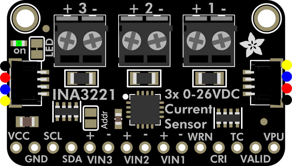
 Design with Adafruit INA3221 - Triple 0-26 VDC, ±3.2 Amp Power Monitor - STEMMA QT / Qwiic in Cirkit Designer
Introduction
The Adafruit INA3221 (Manufacturer Part ID: 6062) is a highly versatile power monitoring module designed to measure voltage and current across three independent channels. With a measurement range of 0-26 VDC and ±3.2 Amps per channel, this component is ideal for monitoring multiple power sources or loads in a single project. It communicates via the I2C protocol and features STEMMA QT / Qwiic connectors for seamless integration into modern electronics projects.
Explore Projects Built with Adafruit INA3221 - Triple 0-26 VDC, ±3.2 Amp Power Monitor - STEMMA QT / Qwiic
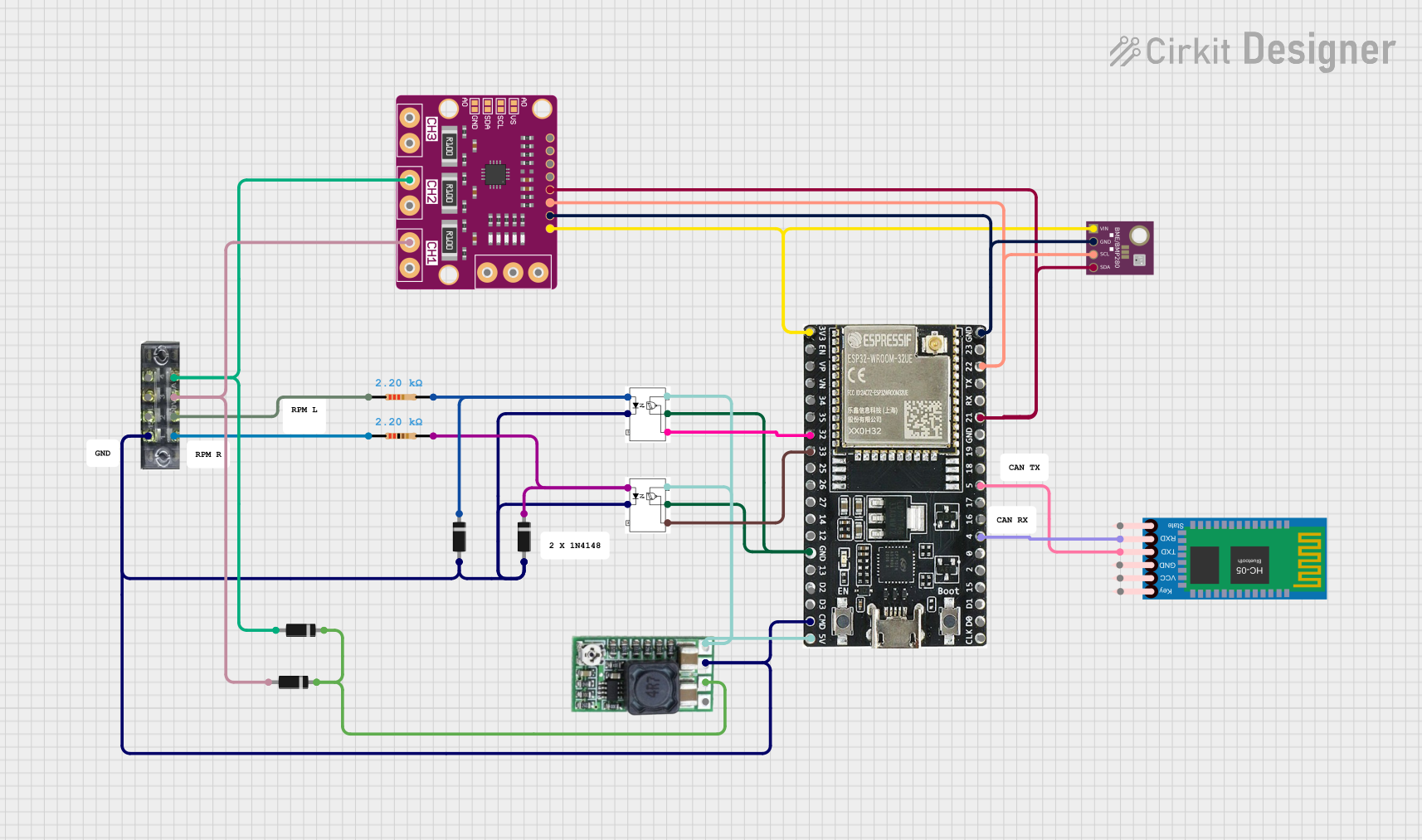 Open Project in Cirkit Designer
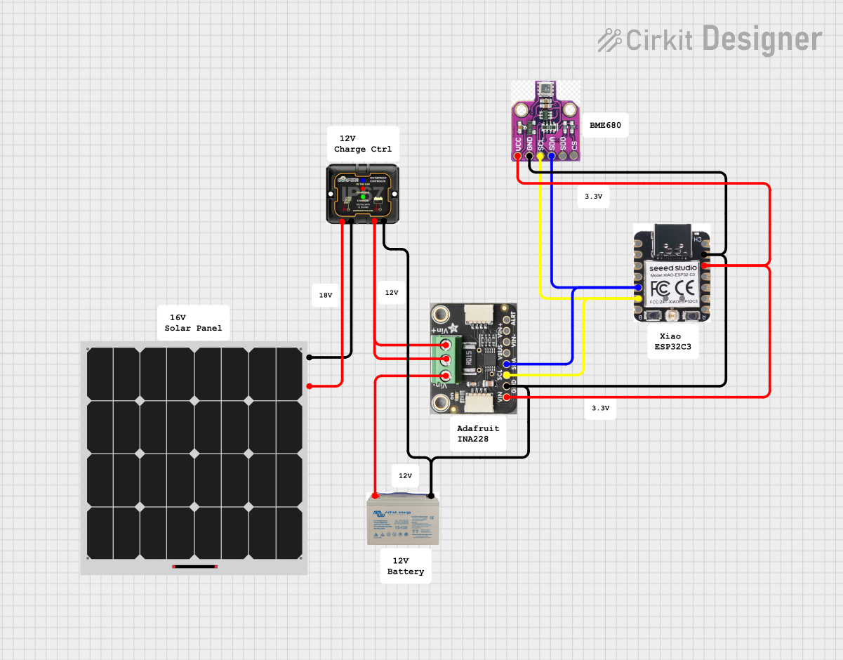 Open Project in Cirkit Designer
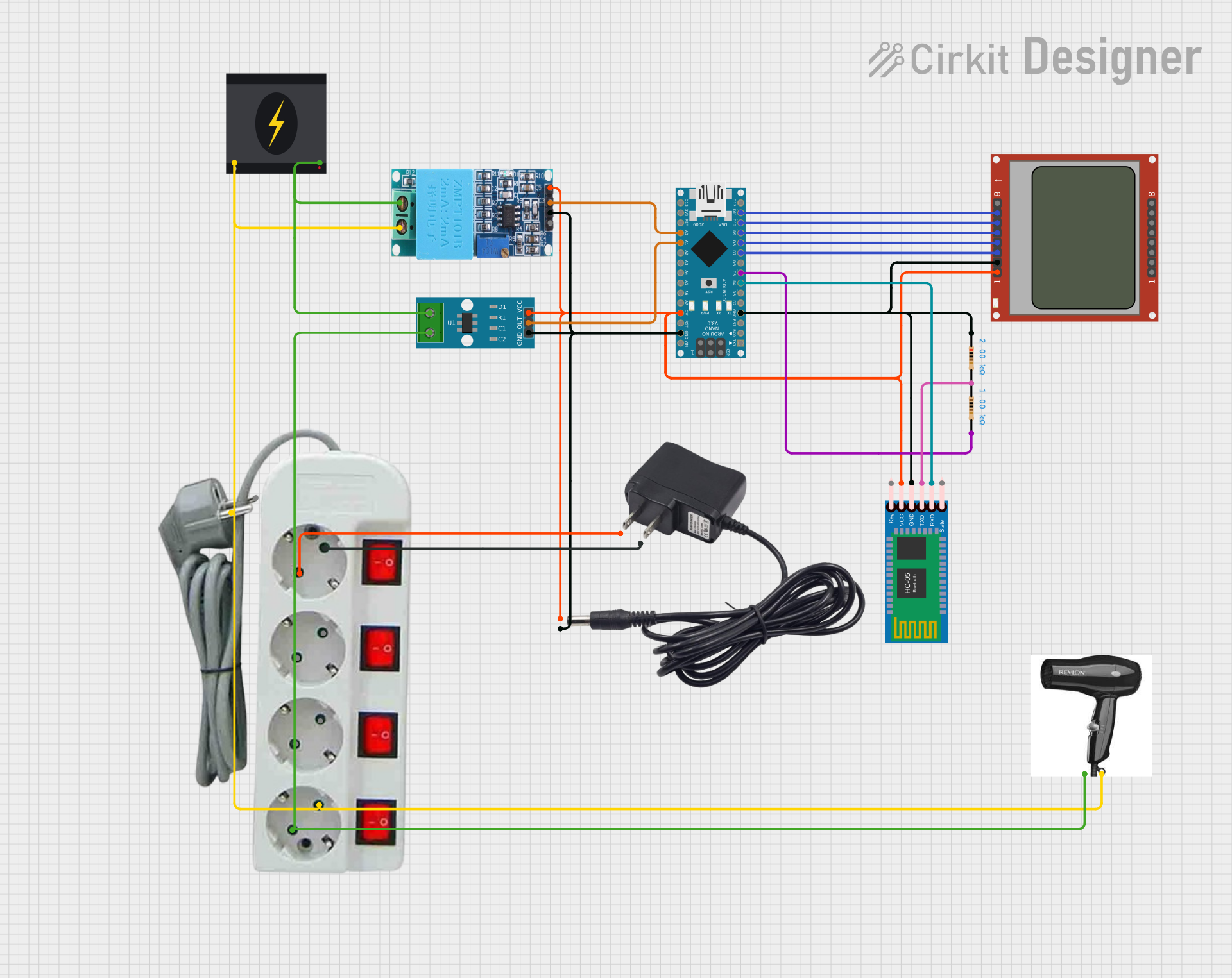 Open Project in Cirkit Designer
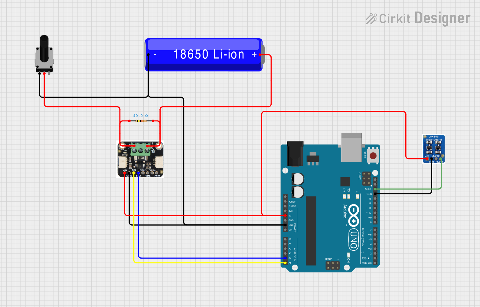 Open Project in Cirkit Designer
Explore Projects Built with Adafruit INA3221 - Triple 0-26 VDC, ±3.2 Amp Power Monitor - STEMMA QT / Qwiic
Open Project in Cirkit DesignerOpen Project in Cirkit DesignerOpen Project in Cirkit DesignerOpen Project in Cirkit DesignerCommon Applications and Use Cases
- Monitoring power consumption in multi-channel systems
- Battery management and diagnostics
- Solar power monitoring
- Robotics and IoT projects requiring real-time power data
- General-purpose voltage and current measurement in electronics
Technical Specifications
The following table outlines the key technical details of the Adafruit INA3221:
| Parameter | Value |
|---|---|
| Operating Voltage | 3.3V or 5V (via I2C bus) |
| Voltage Measurement Range | 0-26 VDC |
| Current Measurement Range | ±3.2 Amps per channel |
| Communication Protocol | I2C |
| Default I2C Address | 0x40 |
| Channels | 3 |
| Connectors | STEMMA QT / Qwiic |
| Dimensions | 25mm x 25mm x 4mm |
| Weight | 2g |
Pin Configuration and Descriptions
The Adafruit INA3221 features the following pins:
| Pin Name | Description |
|---|---|
| VIN+ (x3) | Positive voltage input for each of the three channels. |
| VIN- (x3) | Negative voltage input for each of the three channels. |
| SDA | I2C data line for communication. |
| SCL | I2C clock line for communication. |
| GND | Ground connection. |
| VCC | Power input for the module (3.3V or 5V, typically supplied by the I2C master). |
Usage Instructions
How to Use the Component in a Circuit
- Power the Module: Connect the VCC pin to a 3.3V or 5V power source and the GND pin to ground.
- Connect to I2C: Use the SDA and SCL pins to connect the module to your microcontroller's I2C bus. Alternatively, use the STEMMA QT / Qwiic connectors for a plug-and-play setup.
- Connect the Channels: Attach the positive and negative terminals of the power sources or loads you want to monitor to the VIN+ and VIN- pins of each channel.
- Configure the I2C Address (Optional): If using multiple INA3221 modules, you can change the I2C address by modifying the address pins (refer to the datasheet for details).
- Install Required Libraries: For Arduino, install the Adafruit INA3221 library via the Arduino Library Manager.
Important Considerations and Best Practices
- Ensure that the voltage and current being measured do not exceed the module's maximum ratings (26 VDC and ±3.2 Amps).
- Use appropriate wiring and connectors to handle the current levels safely.
- Avoid connecting the module to power sources with high noise or spikes without proper filtering.
- If using multiple INA3221 modules, ensure each has a unique I2C address to avoid communication conflicts.
Example Arduino Code
Below is an example of how to use the Adafruit INA3221 with an Arduino UNO to read voltage and current from all three channels:
#include <Wire.h>
#include "Adafruit_INA3221.h"

// Create an instance of the INA3221 class
Adafruit_INA3221 ina3221;

// Setup function to initialize the INA3221
void setup() {
  Serial.begin(115200); // Start serial communication for debugging
  while (!Serial) delay(10); // Wait for Serial Monitor to open

  // Initialize the INA3221
  if (!ina3221.begin()) {
    Serial.println("Failed to find INA3221 chip");
    while (1) { delay(10); } // Halt if initialization fails
  }
  Serial.println("INA3221 initialized successfully");
}

// Loop function to read and display data
void loop() {
  for (int i = 0; i < 3; i++) {
    // Read voltage and current for each channel
    float busVoltage = ina3221.getBusVoltage_V(i);
    float current = ina3221.getCurrent_mA(i);

    // Print the results to the Serial Monitor
    Serial.print("Channel ");
    Serial.print(i + 1);
    Serial.print(": Bus Voltage = ");
    Serial.print(busVoltage);
    Serial.print(" V, Current = ");
    Serial.print(current);
    Serial.println(" mA");
  }
  delay(1000); // Wait 1 second before the next reading
}
Troubleshooting and FAQs
Common Issues and Solutions
Module Not Detected on I2C Bus:
- Ensure the SDA and SCL lines are correctly connected to the microcontroller.
- Verify that the I2C address matches the one configured in the code (default is 0x40).
- Check for loose connections or damaged wires.
Incorrect Voltage or Current Readings:
- Confirm that the input voltage and current are within the module's measurement range.
- Ensure proper calibration of the INA3221 (refer to the library documentation for calibration details).
- Verify that the power source or load is connected correctly to the VIN+ and VIN- pins.
Overheating or Damage:
- Avoid exceeding the maximum voltage (26 VDC) or current (±3.2 Amps) ratings.
- Use appropriate heat dissipation methods if measuring high currents for extended periods.
FAQs
Q: Can I use the INA3221 with a Raspberry Pi?
A: Yes, the INA3221 is compatible with Raspberry Pi. Use the I2C pins on the Raspberry Pi and install the appropriate Python libraries (e.g., Adafruit CircuitPython INA3221).
Q: How do I change the I2C address?
A: The INA3221 supports multiple I2C addresses. Refer to the datasheet for instructions on configuring the address pins to set a new address.
Q: Can I measure negative voltages?
A: No, the INA3221 is designed to measure positive voltages only (0-26 VDC). However, it can measure bidirectional currents (±3.2 Amps).
Q: What is the accuracy of the measurements?
A: The INA3221 provides high accuracy, but the exact values depend on the shunt resistor used and the calibration settings. Refer to the datasheet for detailed accuracy specifications.