Cirkit Designer Logo
Cirkit Designer
Your all-in-one circuit design IDE
Home / 
Component Documentation

How to Use PowerBoost 1000 Basic Terminal Terminal: Examples, Pinouts, and Specs

Image of PowerBoost 1000 Basic Terminal Terminal
Cirkit Designer LogoDesign with PowerBoost 1000 Basic Terminal Terminal in Cirkit Designer

Introduction

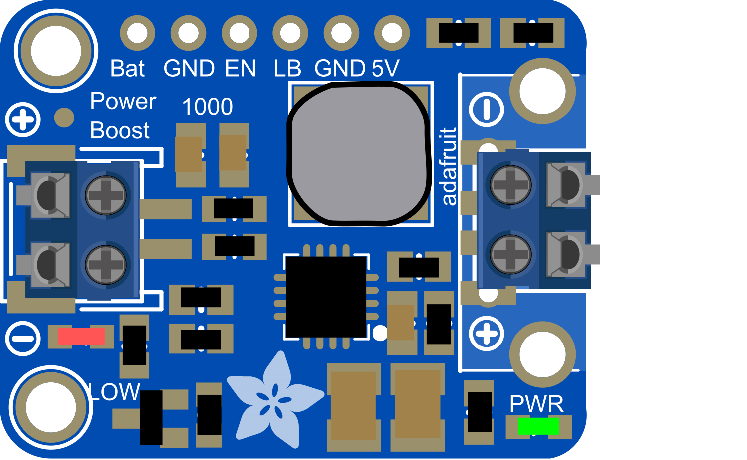
The PowerBoost 1000 Basic is a versatile and efficient power supply module designed to provide a stable 5V output from a single lithium polymer (LiPo) battery. It is equipped with a built-in charging circuit, allowing for easy recharging of the battery. The module includes a terminal block for straightforward connections, making it ideal for portable electronics, DIY projects, and anywhere a compact power source is required.

Explore Projects Built with PowerBoost 1000 Basic Terminal Terminal

Use Cirkit Designer to design, explore, and prototype these projects online. Some projects support real-time simulation. Click "Open Project" to start designing instantly!
Arduino Mega 2560 Based Security System with Fingerprint Authentication and SMS Alerts
Image of Door security system: A project utilizing PowerBoost 1000 Basic Terminal Terminal in a practical application
This circuit features an Arduino Mega 2560 microcontroller interfaced with a SIM800L GSM module, two fingerprint scanners, an I2C LCD display, an IR sensor, and a piezo buzzer. Power management is handled by a PowerBoost 1000 Basic Pad USB, a TP4056 charging module, and a Li-ion 18650 battery, with an option to use a Mini AC-DC 110V-230V to 5V 700mA module for direct power supply. The primary functionality appears to be a security system with GSM communication capabilities, biometric access control, and visual/audible feedback.
Cirkit Designer LogoOpen Project in Cirkit Designer
Modular Power Distribution System with Multiple SMPS Units and 120V Outlet
Image of Cellion-Tesla: A project utilizing PowerBoost 1000 Basic Terminal Terminal in a practical application
This circuit is designed to convert 240V AC power to both 12V and 24V DC outputs using multiple SMPS units. Terminal blocks are used to organize and distribute the power, while a 120V outlet provides additional AC power access. The circuit is likely used for powering various electronic devices that require different voltage levels.
Cirkit Designer LogoOpen Project in Cirkit Designer
Battery-Powered DC/DC Booster with Tactile Switch Control
Image of circuit : A project utilizing PowerBoost 1000 Basic Terminal Terminal in a practical application
This circuit consists of a battery-powered DC/DC booster that steps up the voltage, which is then controlled by a tactile switch. The booster is connected to a copper coil, and the switch allows the user to control the output voltage from the booster.
Cirkit Designer LogoOpen Project in Cirkit Designer
Multi-Stage Voltage Regulation and Indicator LED Circuit
Image of Subramanyak_Power_Circuit: A project utilizing PowerBoost 1000 Basic Terminal Terminal in a practical application
This circuit is designed for power management, featuring buck and boost converters for voltage adjustment, and linear regulators for stable voltage output. It includes LEDs for status indication, and terminal blocks for external connections.
Cirkit Designer LogoOpen Project in Cirkit Designer

Explore Projects Built with PowerBoost 1000 Basic Terminal Terminal

Use Cirkit Designer to design, explore, and prototype these projects online. Some projects support real-time simulation. Click "Open Project" to start designing instantly!
Image of Door security system: A project utilizing PowerBoost 1000 Basic Terminal Terminal in a practical application
Arduino Mega 2560 Based Security System with Fingerprint Authentication and SMS Alerts
This circuit features an Arduino Mega 2560 microcontroller interfaced with a SIM800L GSM module, two fingerprint scanners, an I2C LCD display, an IR sensor, and a piezo buzzer. Power management is handled by a PowerBoost 1000 Basic Pad USB, a TP4056 charging module, and a Li-ion 18650 battery, with an option to use a Mini AC-DC 110V-230V to 5V 700mA module for direct power supply. The primary functionality appears to be a security system with GSM communication capabilities, biometric access control, and visual/audible feedback.
Cirkit Designer LogoOpen Project in Cirkit Designer
Image of Cellion-Tesla: A project utilizing PowerBoost 1000 Basic Terminal Terminal in a practical application
Modular Power Distribution System with Multiple SMPS Units and 120V Outlet
This circuit is designed to convert 240V AC power to both 12V and 24V DC outputs using multiple SMPS units. Terminal blocks are used to organize and distribute the power, while a 120V outlet provides additional AC power access. The circuit is likely used for powering various electronic devices that require different voltage levels.
Cirkit Designer LogoOpen Project in Cirkit Designer
Image of circuit : A project utilizing PowerBoost 1000 Basic Terminal Terminal in a practical application
Battery-Powered DC/DC Booster with Tactile Switch Control
This circuit consists of a battery-powered DC/DC booster that steps up the voltage, which is then controlled by a tactile switch. The booster is connected to a copper coil, and the switch allows the user to control the output voltage from the booster.
Cirkit Designer LogoOpen Project in Cirkit Designer
Image of Subramanyak_Power_Circuit: A project utilizing PowerBoost 1000 Basic Terminal Terminal in a practical application
Multi-Stage Voltage Regulation and Indicator LED Circuit
This circuit is designed for power management, featuring buck and boost converters for voltage adjustment, and linear regulators for stable voltage output. It includes LEDs for status indication, and terminal blocks for external connections.
Cirkit Designer LogoOpen Project in Cirkit Designer

Common Applications and Use Cases

  • Portable USB chargers
  • Battery-powered electronics
  • Wearable devices
  • DIY projects requiring a 5V power supply
  • Raspberry Pi or Arduino portable projects

Technical Specifications

Key Technical Details

  • Input Voltage: 3.7V nominal (LiPo battery voltage)
  • Output Voltage: 5V regulated output
  • Maximum Output Current: 1A continuous, 2A peak
  • Charging Current: 1A maximum
  • Quiescent Current: <5mA

Pin Configuration and Descriptions

Pin Number Name Description
1 BAT Battery input terminal for LiPo battery (+)
2 GND Ground terminal
3 5V Regulated 5V output terminal
4 EN Enable pin (pull low to disable, floating/high to enable)
5 GND Ground terminal for enable pin

Usage Instructions

How to Use the Component in a Circuit

  1. Connecting the Battery:

    • Connect the positive terminal of the LiPo battery to the BAT pin.
    • Connect the negative terminal of the battery to one of the GND pins.
  2. Drawing Power:

    • Connect the device that requires 5V to the 5V and GND terminals.
  3. Enabling/Disabling the Module:

    • To enable the PowerBoost 1000 Basic, leave the EN pin floating or connect it to a high signal.
    • To disable the module, connect the EN pin to GND.

Important Considerations and Best Practices

  • Always ensure the polarity of the battery is correct to prevent damage.
  • Do not exceed the maximum input and output current ratings.
  • Avoid placing the module in environments with extreme temperatures.
  • When charging the battery, use a quality LiPo charger and follow all safety protocols.
  • Ensure proper ventilation around the module to prevent overheating during operation.

Troubleshooting and FAQs

Common Issues

  • Module Not Powering On:

    • Check battery polarity and connections.
    • Ensure the EN pin is not pulled low inadvertently.
  • Insufficient Output Current:

    • Verify that the load does not exceed the 1A continuous or 2A peak current rating.

Solutions and Tips for Troubleshooting

  • If the module does not power on, check the battery charge and connections.
  • For output current issues, reduce the load or check for shorts in the circuit.
  • If the module overheats, ensure there is adequate airflow and consider adding a heatsink.

FAQs

Q: Can I use the PowerBoost 1000 Basic to charge the battery? A: Yes, the module includes a built-in charging circuit for LiPo batteries.

Q: What should I do if the module gets hot during use? A: Ensure proper ventilation and check if the current draw is within the specified limits.

Q: Is it possible to disable the PowerBoost 1000 Basic when not in use? A: Yes, you can disable the module by connecting the EN pin to GND.

Example Code for Arduino UNO

// Example code to control the PowerBoost 1000 Basic with an Arduino UNO

const int enablePin = 2; // Connect to the EN pin of the PowerBoost

void setup() {
  pinMode(enablePin, OUTPUT);
  // Start with the PowerBoost disabled
  digitalWrite(enablePin, LOW);
}

void loop() {
  // Enable the PowerBoost
  digitalWrite(enablePin, HIGH);
  delay(5000); // Keep enabled for 5 seconds

  // Disable the PowerBoost
  digitalWrite(enablePin, LOW);
  delay(5000); // Keep disabled for 5 seconds
}

Note: This example assumes you have connected the EN pin of the PowerBoost 1000 Basic to digital pin 2 on the Arduino UNO. The code enables the PowerBoost for 5 seconds and then disables it for 5 seconds in a loop.