How to Use ENCODER N20: Examples, Pinouts, and Specs
Introduction
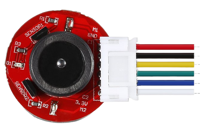
The ENCODER N20 is a rotary encoder designed to convert the angular position or motion of a shaft into an electrical signal. This component is widely used in robotics, automation systems, and motor control applications where precise position feedback is required. Its compact size and compatibility with small DC motors make it an ideal choice for projects requiring accurate rotational measurements.
Explore Projects Built with ENCODER N20
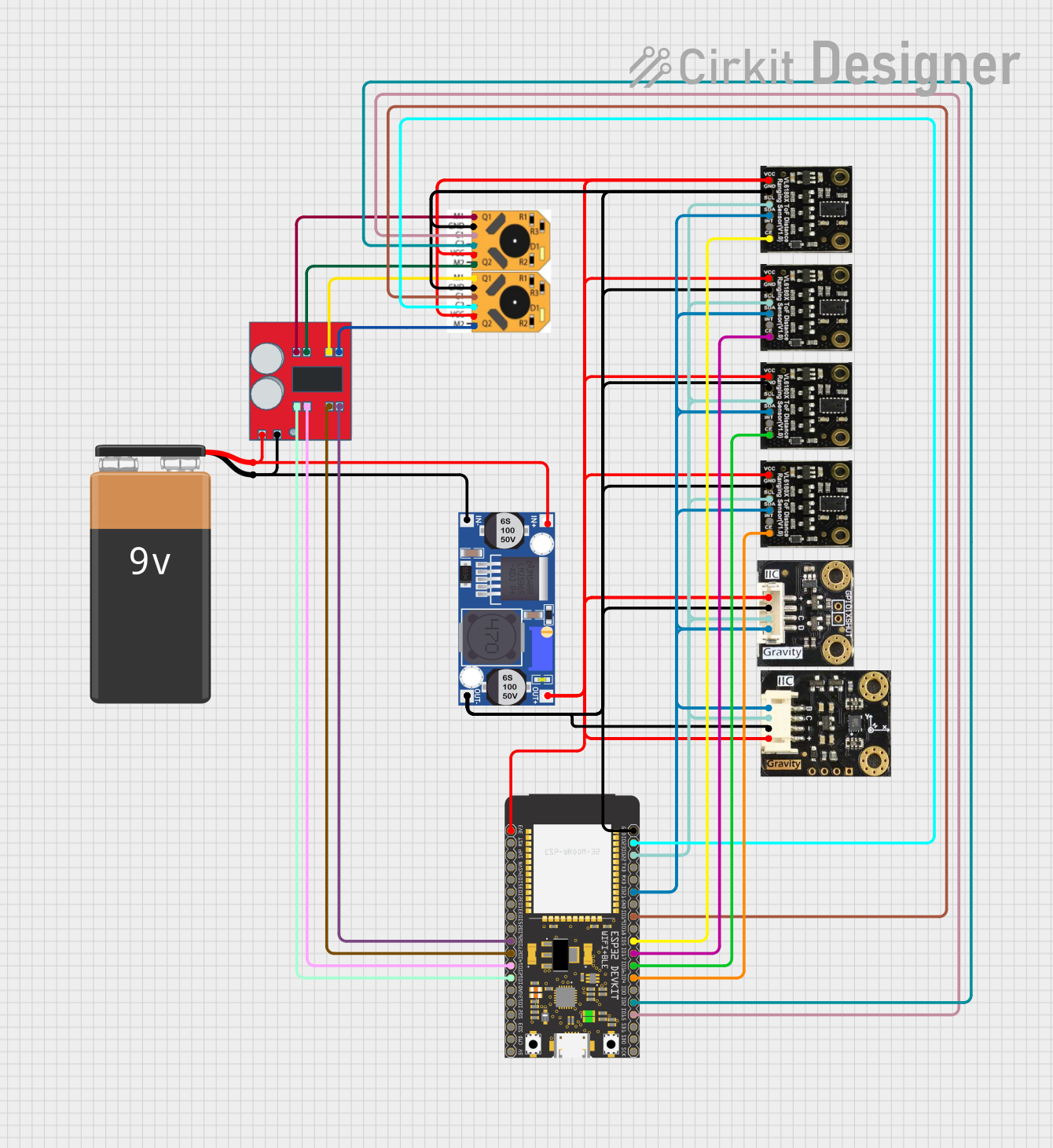


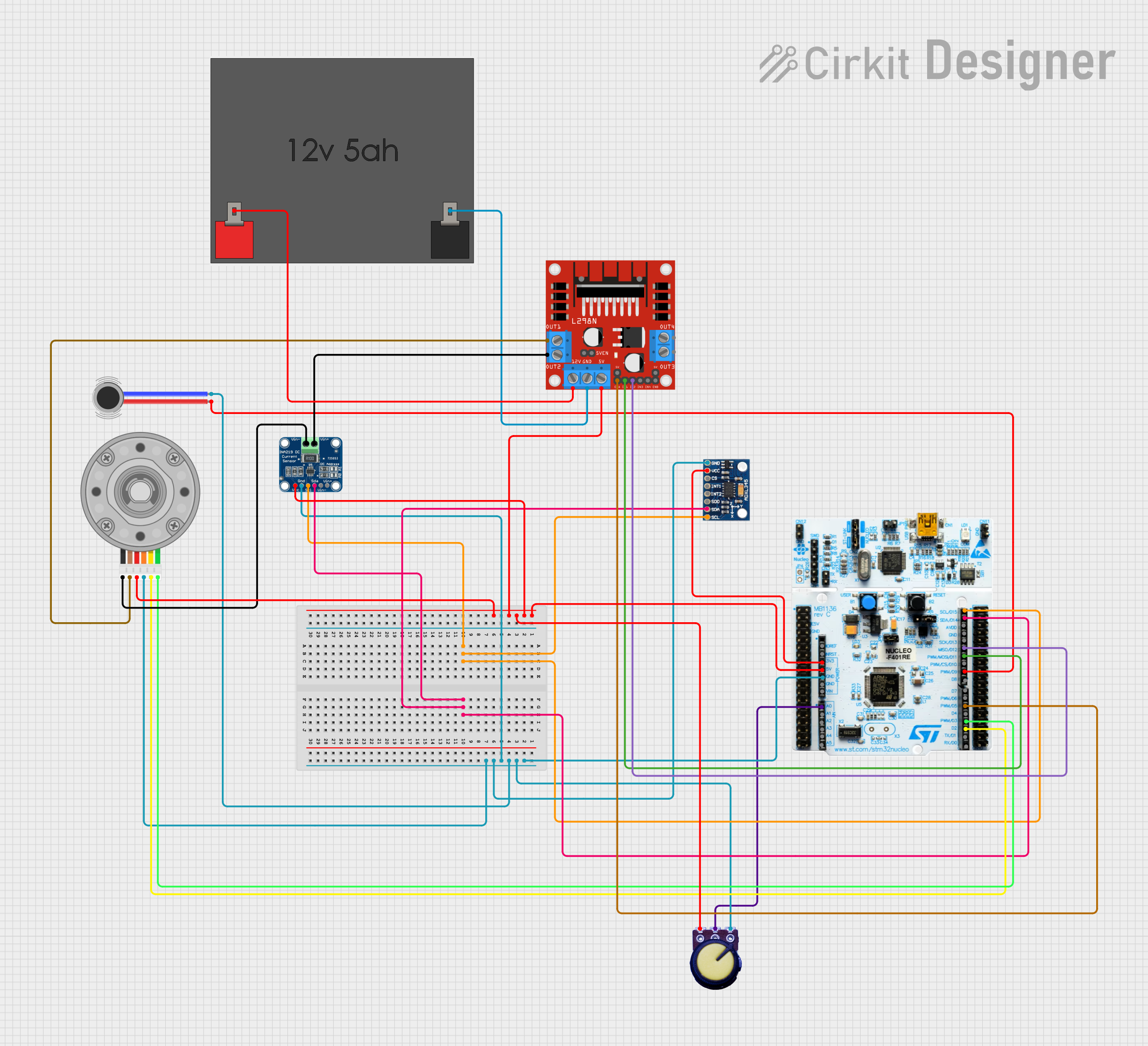
Explore Projects Built with ENCODER N20
Common Applications
- Robotics: For motor position feedback and control.
- Automation: Used in conveyor systems and industrial machinery.
- Motorized systems: Provides feedback for speed and position in DC motor applications.
- DIY projects: Ideal for hobbyists building robotic arms, vehicles, or other motion-based systems.
Technical Specifications
The ENCODER N20 is typically paired with an N20 DC motor and provides incremental position feedback. Below are its key technical details:
General Specifications
| Parameter | Value |
|---|---|
| Operating Voltage | 3.3V to 5V |
| Output Signal Type | Quadrature (A and B channels) |
| Resolution | 11 pulses per revolution (PPR) |
| Maximum Speed | 10,000 RPM |
| Operating Temperature | -20°C to 85°C |
| Dimensions | 12mm x 10mm x 10mm |
Pin Configuration
The ENCODER N20 typically has four output pins. The table below describes each pin:
| Pin Number | Pin Name | Description |
|---|---|---|
| 1 | VCC | Power supply input (3.3V to 5V) |
| 2 | GND | Ground connection |
| 3 | A | Channel A output signal (quadrature signal) |
| 4 | B | Channel B output signal (quadrature signal) |
Usage Instructions
How to Use the ENCODER N20 in a Circuit
- Power the Encoder: Connect the VCC pin to a 3.3V or 5V power source and the GND pin to the ground of your circuit.
- Connect Signal Pins: Connect the A and B output pins to the input pins of a microcontroller (e.g., Arduino UNO) or a motor driver capable of reading quadrature signals.
- Read the Signals: Use the quadrature signals from pins A and B to determine the direction and position of the shaft. The phase difference between the two signals indicates the direction of rotation.
Important Considerations
- Debouncing: The encoder signals may require debouncing to ensure accurate readings. Use hardware filters or software algorithms to handle signal noise.
- Pull-up Resistors: If the encoder outputs are open-drain, you may need to add pull-up resistors to the A and B pins.
- Speed Limitations: Ensure the microcontroller can handle the encoder's maximum pulse rate, especially at high RPMs.
Example: Connecting ENCODER N20 to Arduino UNO
Below is an example Arduino sketch to read the ENCODER N20 signals and calculate the position:
// ENCODER N20 Example Code for Arduino UNO
// This code reads the quadrature signals from the encoder and calculates position.

#define ENCODER_PIN_A 2  // Connect to encoder pin A
#define ENCODER_PIN_B 3  // Connect to encoder pin B

volatile int position = 0;  // Variable to store the encoder position

void setup() {
  pinMode(ENCODER_PIN_A, INPUT);  // Set pin A as input
  pinMode(ENCODER_PIN_B, INPUT);  // Set pin B as input

  // Attach interrupts to handle encoder signals
  attachInterrupt(digitalPinToInterrupt(ENCODER_PIN_A), encoderISR, CHANGE);

  Serial.begin(9600);  // Initialize serial communication
}

void loop() {
  // Print the current position to the Serial Monitor
  Serial.print("Position: ");
  Serial.println(position);
  delay(100);  // Delay for readability
}

// Interrupt Service Routine (ISR) for encoder
void encoderISR() {
  // Read the state of pin A and pin B
  int stateA = digitalRead(ENCODER_PIN_A);
  int stateB = digitalRead(ENCODER_PIN_B);

  // Determine direction based on the state of A and B
  if (stateA == stateB) {
    position++;  // Clockwise rotation
  } else {
    position--;  // Counterclockwise rotation
  }
}
Notes:
- Ensure the encoder pins are connected to interrupt-capable pins on the Arduino (e.g., pins 2 and 3 on the UNO).
- Use the Serial Monitor to observe the position changes as the encoder shaft rotates.
Troubleshooting and FAQs
Common Issues
No Signal Output:
- Check the power supply voltage (3.3V to 5V) and ensure proper connections.
- Verify that the ground (GND) is shared between the encoder and the microcontroller.
Incorrect Position Readings:
- Ensure the A and B pins are connected to the correct microcontroller pins.
- Check for signal noise and consider adding debouncing filters.
Missed Pulses at High Speeds:
- Verify that the microcontroller can handle the encoder's pulse rate.
- Use hardware interrupts for faster signal processing.
FAQs
Q: Can the ENCODER N20 be used with a 12V motor?
A: Yes, the encoder can be used with a 12V motor, but the encoder itself must be powered with 3.3V to 5V.
Q: How do I calculate the RPM of the motor using the encoder?
A: Count the number of pulses in one second, divide by the encoder's PPR (11), and multiply by 60 to get RPM.
Q: Do I need external pull-up resistors?
A: It depends on the encoder's output type. If the outputs are open-drain, you will need pull-up resistors.
By following this documentation, you can effectively integrate the ENCODER N20 into your projects for precise position and motion control.