How to Use 8-channel opto (I/O) interface board (model NSK241): Examples, Pinouts, and Specs
Introduction
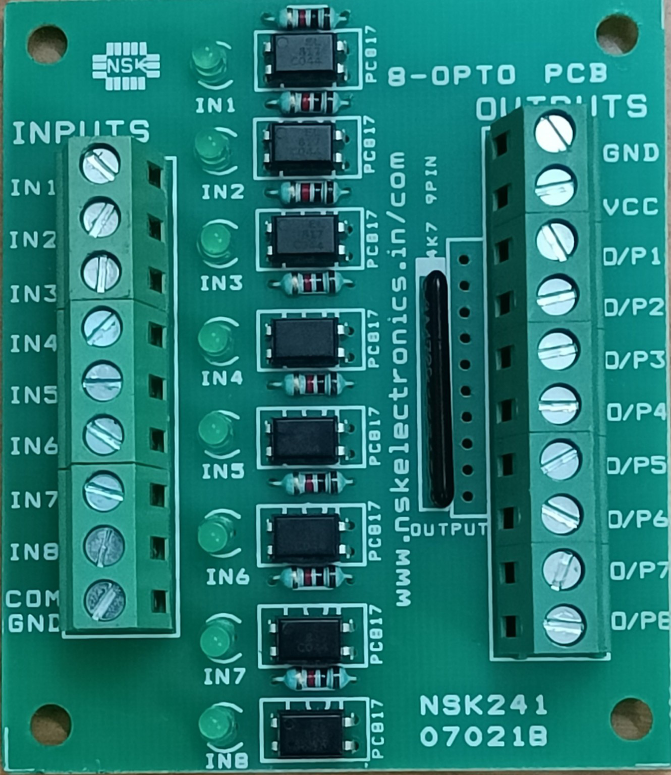
The NSK241 is an 8-channel opto-isolated input/output interface board designed to provide reliable and noise-free connections between microcontrollers, sensors, and actuators. By utilizing optical isolation, the NSK241 protects sensitive electronic components from voltage spikes, electrical noise, and ground loops, ensuring stable operation in a wide range of applications.
Explore Projects Built with 8-channel opto (I/O) interface board (model NSK241)


Explore Projects Built with 8-channel opto (I/O) interface board (model NSK241)
Common Applications and Use Cases
- Industrial automation systems
- Microcontroller-based projects (e.g., Arduino, Raspberry Pi)
- Signal isolation in noisy environments
- Protection of sensitive circuits from high-voltage transients
- Interfacing with sensors, relays, and other I/O devices
Technical Specifications
The following table outlines the key technical details of the NSK241:
| Parameter | Specification |
|---|---|
| Operating Voltage | 5V to 24V DC |
| Input Channels | 8 opto-isolated inputs |
| Output Channels | 8 opto-isolated outputs |
| Input Voltage Range | 5V to 24V DC |
| Output Voltage Range | 5V to 24V DC |
| Maximum Output Current | 50mA per channel |
| Isolation Voltage | 2500V (optical isolation) |
| Board Dimensions | 100mm x 60mm x 20mm |
| Connector Type | Screw terminals for I/O connections |
| Operating Temperature | -20°C to 70°C |
Pin Configuration and Descriptions
The NSK241 features screw terminal connectors for both input and output channels. The pin configuration is as follows:
Input Channels
| Pin | Label | Description |
|---|---|---|
| 1 | IN1 | Opto-isolated input channel 1 |
| 2 | IN2 | Opto-isolated input channel 2 |
| 3 | IN3 | Opto-isolated input channel 3 |
| 4 | IN4 | Opto-isolated input channel 4 |
| 5 | IN5 | Opto-isolated input channel 5 |
| 6 | IN6 | Opto-isolated input channel 6 |
| 7 | IN7 | Opto-isolated input channel 7 |
| 8 | IN8 | Opto-isolated input channel 8 |
Output Channels
| Pin | Label | Description |
|---|---|---|
| 1 | OUT1 | Opto-isolated output channel 1 |
| 2 | OUT2 | Opto-isolated output channel 2 |
| 3 | OUT3 | Opto-isolated output channel 3 |
| 4 | OUT4 | Opto-isolated output channel 4 |
| 5 | OUT5 | Opto-isolated output channel 5 |
| 6 | OUT6 | Opto-isolated output channel 6 |
| 7 | OUT7 | Opto-isolated output channel 7 |
| 8 | OUT8 | Opto-isolated output channel 8 |
Usage Instructions
How to Use the NSK241 in a Circuit
- Power the Board: Connect a DC power supply (5V to 24V) to the power input terminals of the NSK241.
- Connect Inputs: Attach the input devices (e.g., sensors, switches) to the input channels (IN1 to IN8). Ensure the input voltage is within the specified range (5V to 24V).
- Connect Outputs: Connect the output devices (e.g., relays, LEDs, motors) to the output channels (OUT1 to OUT8). Ensure the output current does not exceed 50mA per channel.
- Interface with a Microcontroller: Use the opto-isolated channels to safely interface the NSK241 with a microcontroller (e.g., Arduino UNO).
Important Considerations and Best Practices
- Power Supply: Ensure the power supply voltage matches the requirements of the board and connected devices.
- Isolation: Do not directly connect the input and output grounds; the optical isolation is designed to prevent ground loops.
- Current Limiting: Use appropriate resistors or current-limiting devices to protect the output channels from overcurrent.
- Testing: Test the board with a multimeter before connecting it to sensitive devices.
Example: Connecting the NSK241 to an Arduino UNO
Below is an example of how to use the NSK241 to read an input signal and control an output device with an Arduino UNO:
Circuit Connections
- Connect the Arduino's 5V and GND pins to the NSK241's power input terminals.
- Connect a sensor to IN1 and a relay to OUT1.
- Connect IN1 and OUT1 to the corresponding Arduino pins (e.g., digital pin 2 for input, digital pin 3 for output).
Arduino Code
// Define input and output pins
const int inputPin = 2;  // Arduino pin connected to NSK241 IN1
const int outputPin = 3; // Arduino pin connected to NSK241 OUT1

void setup() {
  pinMode(inputPin, INPUT);  // Set inputPin as input
  pinMode(outputPin, OUTPUT); // Set outputPin as output
  digitalWrite(outputPin, LOW); // Initialize outputPin to LOW
  Serial.begin(9600); // Start serial communication for debugging
}

void loop() {
  int inputState = digitalRead(inputPin); // Read the state of IN1

  // Print the input state to the Serial Monitor
  Serial.print("Input State: ");
  Serial.println(inputState);

  // Control the output based on the input state
  if (inputState == HIGH) {
    digitalWrite(outputPin, HIGH); // Turn ON the output device
  } else {
    digitalWrite(outputPin, LOW); // Turn OFF the output device
  }

  delay(100); // Add a small delay for stability
}
Troubleshooting and FAQs
Common Issues and Solutions
No Response from Input or Output Channels
- Cause: Incorrect wiring or insufficient power supply.
- Solution: Double-check all connections and ensure the power supply voltage is within the specified range.
Output Device Not Turning On
- Cause: Output current exceeds the maximum rating (50mA per channel).
- Solution: Use a relay or transistor to drive high-current devices.
Interference or Noise in Signals
- Cause: Ground loops or improper isolation.
- Solution: Ensure proper optical isolation and avoid connecting input and output grounds.
Board Overheating
- Cause: Excessive current draw or high ambient temperature.
- Solution: Reduce the load on the output channels and ensure adequate ventilation.
FAQs
Can the NSK241 handle AC signals?
- No, the NSK241 is designed for DC signals only.
What happens if the input voltage exceeds 24V?
- Exceeding the input voltage range may damage the opto-isolators. Always use a regulated power supply.
Can I use the NSK241 with a 3.3V microcontroller?
- Yes, but ensure the input and output devices are compatible with 3.3V logic levels.
Is it possible to cascade multiple NSK241 boards?
- Yes, multiple boards can be cascaded, but ensure the total current draw does not exceed the power supply capacity.