How to Use E22-400T33S : Examples, Pinouts, and Specs
Introduction
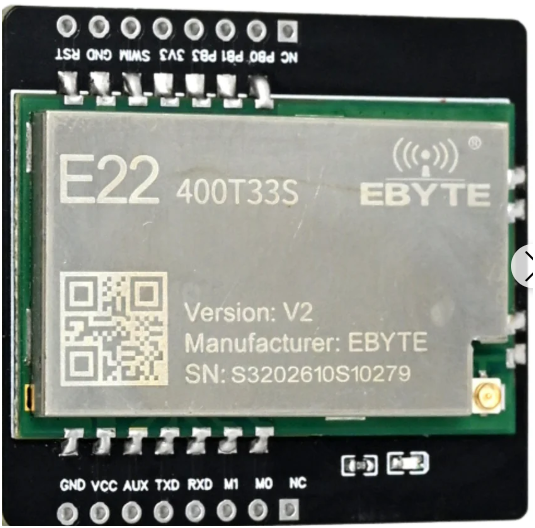
The E22-400T33S is a versatile electronic component, commonly used as a transformer or inductor in power supply applications. It is designed to manage voltage levels efficiently and provide electrical isolation between circuits. This component is ideal for applications requiring reliable energy transfer, such as DC-DC converters, power adapters, and industrial power systems.
Explore Projects Built with E22-400T33S

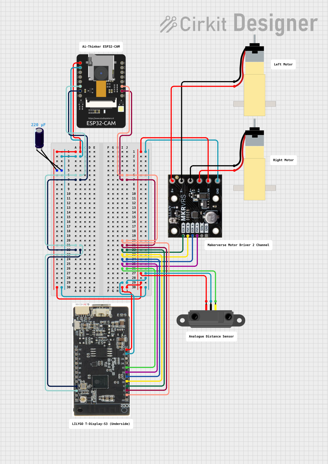


Explore Projects Built with E22-400T33S
Common Applications
- Voltage step-up or step-down in power supply circuits
- Electrical isolation in sensitive electronic systems
- Energy storage in switching power supplies
- Noise filtering in high-frequency circuits
Technical Specifications
The E22-400T33S is engineered to meet the demands of modern power systems. Below are its key technical specifications:
General Specifications
| Parameter | Value |
|---|---|
| Type | Transformer/Inductor |
| Operating Voltage Range | 3.3V to 400V |
| Maximum Current | 3A |
| Power Rating | 10W |
| Operating Frequency | 20 kHz to 1 MHz |
| Operating Temperature | -40°C to +85°C |
| Storage Temperature | -55°C to +125°C |
Pin Configuration
The E22-400T33S typically features a 4-pin configuration. Below is the pinout description:
| Pin Number | Name | Description |
|---|---|---|
| 1 | Primary (+) | Positive terminal of the primary winding |
| 2 | Primary (-) | Negative terminal of the primary winding |
| 3 | Secondary (+) | Positive terminal of the secondary winding |
| 4 | Secondary (-) | Negative terminal of the secondary winding |
Usage Instructions
To use the E22-400T33S in a circuit, follow these steps:
Determine the Application Requirements:
- Identify the input voltage, output voltage, and current requirements of your circuit.
- Ensure the E22-400T33S meets these requirements based on its specifications.
Connect the Component:
- Connect the primary winding (Pin 1 and Pin 2) to the input voltage source.
- Connect the secondary winding (Pin 3 and Pin 4) to the load or output circuit.
Add Supporting Components:
- For transformer applications, use rectifiers and capacitors to convert AC to DC if needed.
- For inductor applications, include appropriate switching components and diodes.
Test the Circuit:
- Verify the output voltage and current using a multimeter.
- Ensure the component does not overheat during operation.
Important Considerations
- Voltage Isolation: Ensure the primary and secondary windings are properly isolated to prevent electrical shorts.
- Frequency Range: Operate the component within the specified frequency range to avoid inefficiencies or damage.
- Thermal Management: Use heat sinks or cooling mechanisms if the component operates near its maximum power rating.
Example: Using E22-400T33S with Arduino UNO
The E22-400T33S can be used in conjunction with an Arduino UNO for power supply applications. Below is an example of how to use it in a basic DC-DC converter circuit:
/*
  Example: Controlling a DC-DC Converter with E22-400T33S
  This code demonstrates how to use an Arduino UNO to control a DC-DC converter
  circuit with the E22-400T33S transformer. The Arduino generates a PWM signal
  to drive a MOSFET, which switches the primary winding of the transformer.
*/

const int pwmPin = 9; // PWM output pin connected to the MOSFET gate

void setup() {
  pinMode(pwmPin, OUTPUT); // Set the PWM pin as an output
}

void loop() {
  // Generate a PWM signal with 50% duty cycle
  analogWrite(pwmPin, 128); // 128 corresponds to 50% duty cycle (0-255 scale)

  // Add a delay to simulate continuous operation
  delay(1000); // 1-second delay
}
Note: Ensure the MOSFET and other components in the circuit are rated for the voltage and current levels used.
Troubleshooting and FAQs
Common Issues
No Output Voltage:
- Cause: Incorrect wiring or loose connections.
- Solution: Double-check the pin connections and ensure proper soldering.
Overheating:
- Cause: Exceeding the power rating or poor thermal management.
- Solution: Reduce the load or add heat sinks to dissipate heat.
Low Efficiency:
- Cause: Operating outside the specified frequency range.
- Solution: Adjust the switching frequency to match the component's optimal range.
Electrical Noise:
- Cause: Insufficient filtering in the circuit.
- Solution: Add capacitors or ferrite beads to reduce noise.
FAQs
Q1: Can the E22-400T33S be used for audio applications?
A1: While primarily designed for power supply applications, it can be used in audio circuits for impedance matching or isolation, provided the frequency range is compatible.
Q2: What is the maximum load the E22-400T33S can handle?
A2: The component can handle a maximum power of 10W, but ensure the current does not exceed 3A.
Q3: How do I calculate the turns ratio for this transformer?
A3: The turns ratio is determined by the input and output voltage requirements. Use the formula:
Turns Ratio = Primary Voltage / Secondary Voltage.
Q4: Is the E22-400T33S suitable for high-frequency switching?
A4: Yes, it supports frequencies up to 1 MHz, making it suitable for high-frequency applications.
By following this documentation, users can effectively integrate the E22-400T33S into their electronic designs and troubleshoot common issues.