Cirkit Designer Logo
Cirkit Designer
Your all-in-one circuit design IDE
Home / 
Component Documentation

How to Use NPN Transistor (CBE): Examples, Pinouts, and Specs

Image of NPN Transistor (CBE)
Cirkit Designer LogoDesign with NPN Transistor (CBE) in Cirkit Designer

Introduction

An NPN transistor is a fundamental electronic component used in various applications to amplify or switch electronic signals. It is a type of bipolar junction transistor (BJT) consisting of three layers of semiconductor material with different doping levels. The acronym 'NPN' refers to the arrangement of these layers: a layer of P-type material is sandwiched between two layers of N-type material. In the CBE (Collector-Base-Emitter) configuration, the transistor's collector (C) is connected to the base (B) through a resistor, which is a common setup for amplification circuits.

Explore Projects Built with NPN Transistor (CBE)

Use Cirkit Designer to design, explore, and prototype these projects online. Some projects support real-time simulation. Click "Open Project" to start designing instantly!
NPN Transistor-Based Voltage Measurement Circuit with Dual Power Supplies
Image of lab9: A project utilizing NPN Transistor (CBE) in a practical application
This circuit is a simple NPN transistor switch configuration powered by two power supplies. It includes resistors to limit current and multimeters to measure voltage and current at various points in the circuit.
Cirkit Designer LogoOpen Project in Cirkit Designer
NPN Transistor-Based Signal Interface with Relimate Connectors
Image of Mini cross: A project utilizing NPN Transistor (CBE) in a practical application
This circuit appears to be a simple transistor-based switching circuit with multiple NPN transistors and resistors, interfaced through relimate connectors. The transistors are likely used to control the flow of current through various parts of the circuit, possibly for switching or amplification purposes, with the relimate connectors providing external connections for power and signal lines.
Cirkit Designer LogoOpen Project in Cirkit Designer
Transistor-Based Signal Modulation Circuit with AC/DC Power Integration
Image of PPPPP: A project utilizing NPN Transistor (CBE) in a practical application
This circuit appears to be a transistor-based switching or amplification system powered by a 12v battery, with an AC supply possibly for signal input or additional power. It includes filtering through ceramic capacitors and uses resistors for biasing the transistors. The presence of both PNP and NPN transistors suggests a push-pull configuration or a form of signal modulation.
Cirkit Designer LogoOpen Project in Cirkit Designer
Battery-Powered LED Control Circuit with NPN Transistors and DIP Switches
Image of Personal Project: half adder works: A project utilizing NPN Transistor (CBE) in a practical application
This circuit is a complex transistor-based switching network controlled by two 4-position DIP switches. It includes multiple NPN transistors, resistors, and LEDs, with the transistors acting as switches to control the LEDs based on the DIP switch settings, powered by a battery.
Cirkit Designer LogoOpen Project in Cirkit Designer

Explore Projects Built with NPN Transistor (CBE)

Use Cirkit Designer to design, explore, and prototype these projects online. Some projects support real-time simulation. Click "Open Project" to start designing instantly!
Image of lab9: A project utilizing NPN Transistor (CBE) in a practical application
NPN Transistor-Based Voltage Measurement Circuit with Dual Power Supplies
This circuit is a simple NPN transistor switch configuration powered by two power supplies. It includes resistors to limit current and multimeters to measure voltage and current at various points in the circuit.
Cirkit Designer LogoOpen Project in Cirkit Designer
Image of Mini cross: A project utilizing NPN Transistor (CBE) in a practical application
NPN Transistor-Based Signal Interface with Relimate Connectors
This circuit appears to be a simple transistor-based switching circuit with multiple NPN transistors and resistors, interfaced through relimate connectors. The transistors are likely used to control the flow of current through various parts of the circuit, possibly for switching or amplification purposes, with the relimate connectors providing external connections for power and signal lines.
Cirkit Designer LogoOpen Project in Cirkit Designer
Image of PPPPP: A project utilizing NPN Transistor (CBE) in a practical application
Transistor-Based Signal Modulation Circuit with AC/DC Power Integration
This circuit appears to be a transistor-based switching or amplification system powered by a 12v battery, with an AC supply possibly for signal input or additional power. It includes filtering through ceramic capacitors and uses resistors for biasing the transistors. The presence of both PNP and NPN transistors suggests a push-pull configuration or a form of signal modulation.
Cirkit Designer LogoOpen Project in Cirkit Designer
Image of Personal Project: half adder works: A project utilizing NPN Transistor (CBE) in a practical application
Battery-Powered LED Control Circuit with NPN Transistors and DIP Switches
This circuit is a complex transistor-based switching network controlled by two 4-position DIP switches. It includes multiple NPN transistors, resistors, and LEDs, with the transistors acting as switches to control the LEDs based on the DIP switch settings, powered by a battery.
Cirkit Designer LogoOpen Project in Cirkit Designer

Common Applications and Use Cases

  • Signal amplification in audio devices
  • Switching operations in digital circuits
  • Voltage regulation
  • Driving motors and relays

Technical Specifications

Key Technical Details

  • Maximum Collector-Emitter Voltage (Vce): The maximum voltage the transistor can handle between the collector and emitter without damage.
  • Maximum Collector Current (Ic): The maximum current that can flow through the collector terminal.
  • Power Dissipation (Pd): The maximum power the transistor can dissipate without overheating.
  • Gain Bandwidth Product (fT): The frequency at which the current gain drops to one.

Pin Configuration and Descriptions

Pin Number Name Description
1 Emitter (E) Emits electrons into the base region. Connected to ground in NPN circuits.
2 Base (B) Controls the transistor's operation. A small current to the base allows a larger current to flow between the collector and emitter.
3 Collector (C) Collects electrons from the base. Typically connected to the load and power supply.

Usage Instructions

How to Use the Component in a Circuit

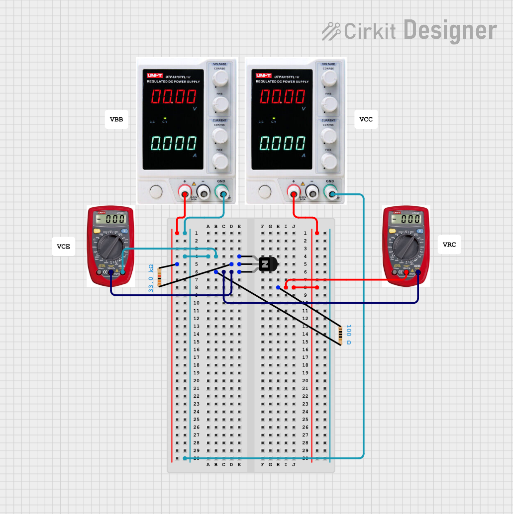
  1. Biasing the Transistor: Apply a small base-emitter voltage (Vbe) to turn on the transistor. This voltage is typically around 0.7V for silicon transistors.
  2. Collector Resistor: Connect a resistor between the collector and the positive supply voltage to limit the collector current.
  3. Emitter: Connect the emitter to the ground.
  4. Input Signal: Apply the input signal to the base of the transistor to be amplified.
  5. Output Signal: The amplified signal can be taken from the collector of the transistor.

Important Considerations and Best Practices

  • Ensure that the transistor's maximum ratings are not exceeded to prevent damage.
  • Use a current-limiting resistor at the base to prevent excessive base current.
  • Provide adequate heat sinking if the transistor is expected to dissipate significant power.

Troubleshooting and FAQs

Common Issues Users Might Face

  • Transistor Not Switching: Ensure that the base-emitter voltage is sufficient to turn on the transistor.
  • Excessive Heat: Check if the power dissipation exceeds the transistor's rating. Add a heat sink if necessary.
  • Low Amplification: Verify that the transistor is not in saturation or cutoff and that the load is appropriate for the desired amplification.

Solutions and Tips for Troubleshooting

  • Measure the voltages at the base, collector, and emitter to ensure they are within expected ranges.
  • Check the base current and ensure it is sufficient to drive the collector current needed for your application.
  • If the transistor is overheating, reduce the power dissipation by lowering the collector current or improving heat sinking.

Example Code for Arduino UNO

// Example code to use an NPN transistor to switch an LED on and off with Arduino UNO

const int basePin = 2; // Pin connected to the base of the transistor
const int ledPin =  13; // Pin connected to the collector of the transistor

void setup() {
  pinMode(basePin, OUTPUT); // Initialize the base pin as an output
  pinMode(ledPin, OUTPUT); // Initialize the LED pin as an output
}

void loop() {
  digitalWrite(basePin, HIGH); // Turn on the transistor
  delay(1000); // Wait for 1 second
  digitalWrite(basePin, LOW); // Turn off the transistor
  delay(1000); // Wait for 1 second
}

Note: The above code assumes that there is a suitable resistor in series with the LED to limit the current and that the LED is connected to the collector of the transistor with the emitter grounded. The base resistor is also assumed to be of a suitable value to limit the base current.