How to Use victor spx: Examples, Pinouts, and Specs
Introduction
The Victor SPX is a compact, high-performance motor controller designed for controlling brushed DC motors in robotics and other applications. It is part of the Cross The Road Electronics (CTRE) product line and is widely used in competitive robotics, such as FIRST Robotics Competition (FRC). The Victor SPX offers advanced features like built-in current sensing, support for both PWM and CAN communication, and optimized efficiency for reliable motor control.
Explore Projects Built with victor spx


Explore Projects Built with victor spx
Common Applications and Use Cases
- Robotics (e.g., FRC robots)
- Industrial automation
- Remote-controlled vehicles
- Educational projects involving motor control
- Prototyping and testing of brushed DC motor systems
Technical Specifications
The Victor SPX is designed to deliver reliable performance in demanding environments. Below are its key technical specifications:
| Specification | Value |
|---|---|
| Input Voltage Range | 6V to 16V |
| Continuous Current Rating | 60A |
| Peak Current Rating | 100A (for short durations) |
| Communication Protocols | PWM, CAN |
| Control Resolution | 10-bit (PWM) |
| Dimensions | 2.25" x 1.25" x 0.75" (approx.) |
| Weight | 0.1 lbs (45 grams) |
| Operating Temperature | -20°C to 85°C |
| Built-in Features | Current sensing, thermal protection |
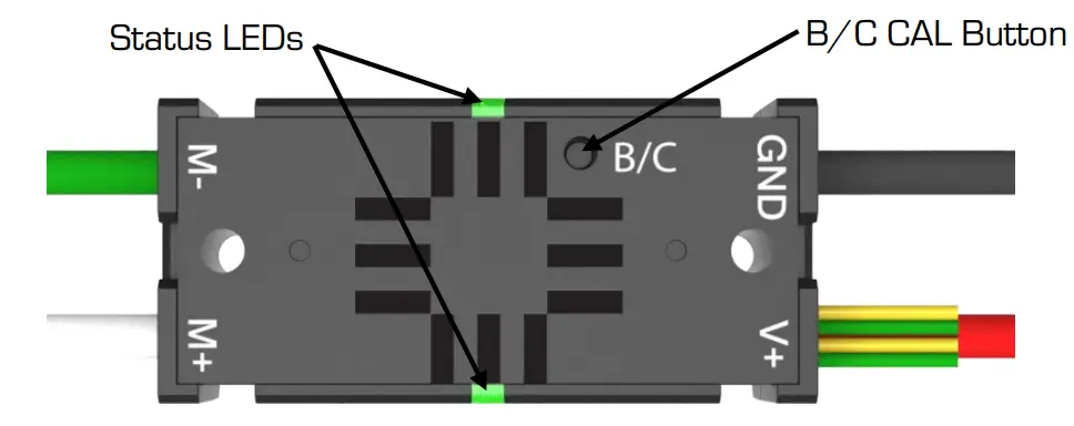
Pin Configuration and Descriptions
The Victor SPX has a simple pinout for easy integration into your system. Below is the pin configuration:
| Pin Name | Description |
|---|---|
| PWM Input | Accepts a standard PWM signal for motor control (1ms to 2ms pulse width). |
| CAN High (CANH) | High line for CAN communication. |
| CAN Low (CANL) | Low line for CAN communication. |
| Motor Output (+) | Positive terminal for connecting the brushed DC motor. |
| Motor Output (-) | Negative terminal for connecting the brushed DC motor. |
| Power Input (+) | Positive terminal for connecting the power supply (6V to 16V). |
| Power Input (-) | Negative terminal for connecting the power supply (ground). |
Usage Instructions
The Victor SPX is versatile and can be used in a variety of configurations. Below are the steps and best practices for using the Victor SPX in a circuit.
Connecting the Victor SPX
- Power Supply: Connect the power supply to the
Power Input (+)andPower Input (-)terminals. Ensure the voltage is within the 6V to 16V range. - Motor Connection: Connect the brushed DC motor to the
Motor Output (+)andMotor Output (-)terminals. - Control Signal:
- For PWM control, connect the PWM signal to the
PWM Inputpin. - For CAN communication, connect the
CAN High (CANH)andCAN Low (CANL)lines to your CAN bus.
- For PWM control, connect the PWM signal to the
- Verify Connections: Double-check all connections to ensure proper polarity and secure wiring.
Important Considerations
- Current Limits: Ensure the motor's current draw does not exceed the Victor SPX's continuous current rating of 60A.
- Thermal Management: Avoid placing the Victor SPX in enclosed spaces without ventilation, as it may overheat under heavy loads.
- PWM Signal: Use a PWM signal with a pulse width between 1ms (full reverse) and 2ms (full forward). A 1.5ms pulse width corresponds to neutral (no movement).
- CAN Configuration: If using CAN communication, ensure the device ID is properly configured using CTRE's Phoenix Tuner software.
Example: Using Victor SPX with Arduino UNO (PWM Control)
Below is an example of how to control a Victor SPX using an Arduino UNO with a PWM signal:
// Example: Controlling Victor SPX with Arduino UNO
// This code generates a PWM signal to control motor speed and direction.

const int pwmPin = 9; // PWM output pin connected to Victor SPX PWM Input

void setup() {
  pinMode(pwmPin, OUTPUT); // Set the PWM pin as an output
}

void loop() {
  // Full forward (2ms pulse width)
  analogWrite(pwmPin, 255); // 100% duty cycle
  delay(2000); // Run for 2 seconds

  // Neutral (1.5ms pulse width)
  analogWrite(pwmPin, 191); // 75% duty cycle (approx. 1.5ms pulse width)
  delay(2000); // Run for 2 seconds

  // Full reverse (1ms pulse width)
  analogWrite(pwmPin, 127); // 50% duty cycle
  delay(2000); // Run for 2 seconds
}
Notes:
- The
analogWrite()function generates a PWM signal with an 8-bit resolution (0-255). - Adjust the duty cycle values to fine-tune the motor's speed and direction.
Troubleshooting and FAQs
Common Issues and Solutions
Motor Not Running
- Cause: Incorrect wiring or no PWM signal.
- Solution: Verify all connections and ensure the PWM signal is within the valid range (1ms to 2ms).
Overheating
- Cause: Excessive current draw or poor ventilation.
- Solution: Check the motor's current requirements and ensure proper airflow around the Victor SPX.
CAN Communication Not Working
- Cause: Incorrect device ID or wiring.
- Solution: Use CTRE's Phoenix Tuner to configure the device ID and verify CAN bus wiring.
Erratic Motor Behavior
- Cause: Noise in the PWM signal or power supply instability.
- Solution: Use shielded cables for the PWM signal and ensure a stable power supply.
FAQs
Q: Can the Victor SPX control brushless motors?
A: No, the Victor SPX is designed specifically for brushed DC motors.
Q: How do I update the firmware on the Victor SPX?
A: Use CTRE's Phoenix Tuner software to update the firmware via the CAN interface.
Q: What is the maximum cable length for the PWM signal?
A: It is recommended to keep the PWM cable length under 3 feet to minimize signal degradation.
Q: Can I use the Victor SPX with a 24V motor?
A: No, the Victor SPX supports a maximum input voltage of 16V. Using a 24V motor may damage the controller.
By following this documentation, you can effectively integrate the Victor SPX into your projects and troubleshoot common issues.