
How to Use 3-Pin Servo Header (Male, 2.54 mm): Examples, Pinouts, and Specs

 Design with 3-Pin Servo Header (Male, 2.54 mm) in Cirkit Designer
Introduction
The 3-Pin Servo Header (Male, 2.54 mm) is a compact and versatile connector designed for interfacing servo motors with electronic circuits. Its 2.54 mm pitch ensures compatibility with standard breadboards, perfboards, and PCBs, making it an essential component for robotics, RC projects, and other servo-controlled applications. This header provides a reliable connection for power, ground, and signal lines, simplifying the integration of servo motors into your designs.
Explore Projects Built with 3-Pin Servo Header (Male, 2.54 mm)
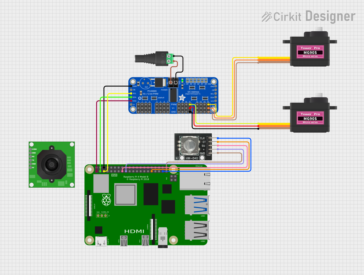 Open Project in Cirkit Designer
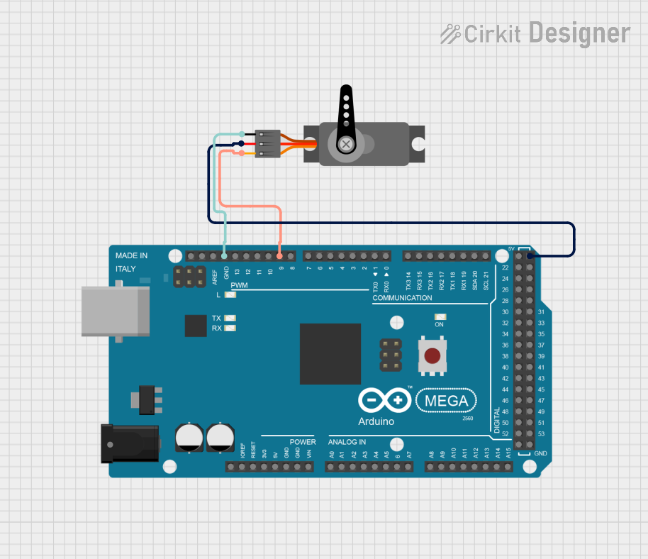 Open Project in Cirkit Designer
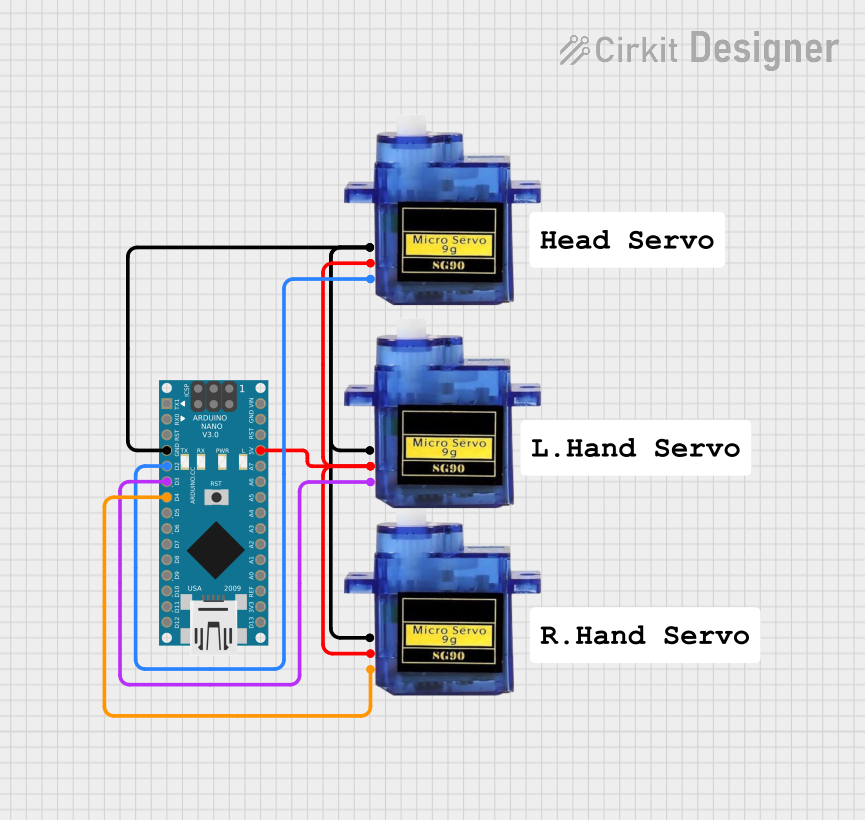 Open Project in Cirkit Designer
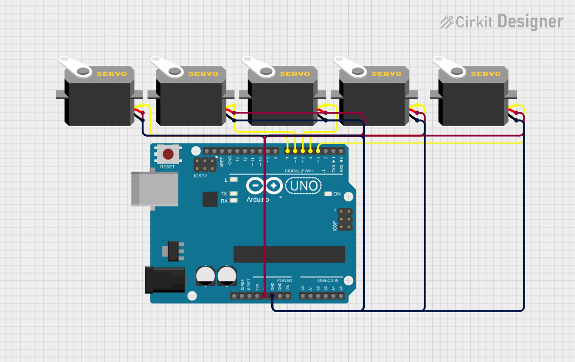 Open Project in Cirkit Designer
Explore Projects Built with 3-Pin Servo Header (Male, 2.54 mm)
Open Project in Cirkit DesignerOpen Project in Cirkit DesignerOpen Project in Cirkit DesignerOpen Project in Cirkit DesignerCommon Applications and Use Cases
- Robotics and automation projects
- Remote-controlled vehicles and drones
- Servo motor testing and prototyping
- DIY electronics and hobbyist projects
- Circuit boards requiring servo motor connections
Technical Specifications
Below are the key technical details of the 3-Pin Servo Header (Male, 2.54 mm):
| Parameter | Specification |
|---|---|
| Pin Count | 3 |
| Pin Type | Male |
| Pitch (Pin Spacing) | 2.54 mm |
| Material | Copper alloy with tin plating |
| Current Rating | Up to 3 A |
| Voltage Rating | Up to 250 V |
| Operating Temperature | -40°C to +105°C |
| Compatibility | Standard breadboards, PCBs, and servos |
Pin Configuration and Descriptions
The 3-pin servo header is typically used to connect servo motors. The pinout is as follows:
| Pin Number | Name | Description |
|---|---|---|
| 1 | Signal | Carries the PWM signal to control the servo motor |
| 2 | VCC | Supplies power to the servo motor (typically 5V) |
| 3 | GND | Ground connection for the servo motor |
Usage Instructions
How to Use the Component in a Circuit
- Insert the Header: Place the 3-pin servo header into a breadboard or solder it onto a PCB.
- Connect the Servo Motor: Plug the servo motor's connector into the header, ensuring proper alignment:
- The signal wire (usually orange or white) connects to the Signal pin.
- The power wire (usually red) connects to the VCC pin.
- The ground wire (usually black or brown) connects to the GND pin.
- Connect to a Microcontroller: Use jumper wires to connect the header's pins to your microcontroller:
- Signal pin to a PWM-capable GPIO pin.
- VCC pin to a 5V power source.
- GND pin to the microcontroller's ground.
Important Considerations and Best Practices
- Check Voltage and Current Ratings: Ensure the servo motor's power requirements match the header's ratings.
- Secure Connections: Use proper soldering techniques or tight breadboard connections to avoid loose contacts.
- Avoid Overloading: Do not exceed the current rating of the header to prevent overheating or damage.
- Use Decoupling Capacitors: Place a capacitor (e.g., 100 µF) across the VCC and GND lines to stabilize the power supply.
Example: Connecting to an Arduino UNO
Below is an example of how to connect a servo motor to an Arduino UNO using the 3-pin servo header:
Circuit Diagram
- Signal pin → Arduino digital pin 9
- VCC pin → Arduino 5V
- GND pin → Arduino GND
Arduino Code
#include <Servo.h> // Include the Servo library

Servo myServo; // Create a Servo object

void setup() {
  myServo.attach(9); // Attach the servo to pin 9
}

void loop() {
  myServo.write(0); // Move servo to 0 degrees
  delay(1000);      // Wait for 1 second
  myServo.write(90); // Move servo to 90 degrees
  delay(1000);      // Wait for 1 second
  myServo.write(180); // Move servo to 180 degrees
  delay(1000);      // Wait for 1 second
}
Troubleshooting and FAQs
Common Issues and Solutions
Servo Motor Not Responding
- Cause: Incorrect wiring or loose connections.
- Solution: Double-check the wiring and ensure the servo motor is properly connected to the header.
Header Overheating
- Cause: Exceeding the current rating of the header.
- Solution: Use a servo motor that operates within the header's current rating (up to 3 A).
Unstable Servo Movement
- Cause: Insufficient power supply or electrical noise.
- Solution: Add a decoupling capacitor across the VCC and GND pins to stabilize the power.
Servo Moves Erratically
- Cause: Incorrect PWM signal or interference.
- Solution: Verify the PWM signal from the microcontroller and ensure proper grounding.
FAQs
Q: Can I use this header for other components besides servo motors?
A: Yes, the 3-pin servo header can be used for any 3-wire connection, such as sensors or LEDs, as long as the voltage and current ratings are not exceeded.
Q: Is this header compatible with microcontrollers other than Arduino?
A: Absolutely! It can be used with any microcontroller that supports PWM signals, such as Raspberry Pi, ESP32, or STM32.
Q: Can I daisy-chain multiple headers for multiple servos?
A: Yes, but ensure the power supply can handle the combined current draw of all connected servos.
Q: What tools are needed to solder this header onto a PCB?
A: You will need a soldering iron, solder wire, and optionally flux for cleaner joints.
This concludes the documentation for the 3-Pin Servo Header (Male, 2.54 mm).