Cirkit Designer Logo
Cirkit Designer
Your all-in-one circuit design IDE
Home / 
Component Documentation

How to Use EMI Filter - CW1B-10A-L (040): Examples, Pinouts, and Specs

Image of EMI Filter - CW1B-10A-L (040)
Cirkit Designer LogoDesign with EMI Filter - CW1B-10A-L (040) in Cirkit Designer

Introduction

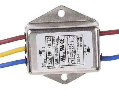
The EMI Filter - CW1B-10A-L (040), manufactured by Shopee, is a high-performance electromagnetic interference (EMI) filter designed to suppress unwanted noise and interference in electronic circuits. This component ensures stable operation of devices and compliance with regulatory standards for electromagnetic compatibility (EMC). Its compact design and robust construction make it suitable for a wide range of applications, including industrial equipment, consumer electronics, and power supplies.

Explore Projects Built with EMI Filter - CW1B-10A-L (040)

Use Cirkit Designer to design, explore, and prototype these projects online. Some projects support real-time simulation. Click "Open Project" to start designing instantly!
Audio Signal Conditioning Circuit with 3.5mm Jacks and Passive Components
Image of BA: A project utilizing EMI Filter - CW1B-10A-L (040) in a practical application
This circuit appears to be an audio signal processing or filtering circuit, utilizing multiple 3.5mm jacks for input and output connections, resistors, and capacitors to form various RC (resistor-capacitor) networks. The configuration suggests it could be used for tasks such as audio signal conditioning, noise filtering, or impedance matching.
Cirkit Designer LogoOpen Project in Cirkit Designer
PNP Transistor-Based Power Regulation Circuit with Multiple Power Supplies
Image of Realistic: A project utilizing EMI Filter - CW1B-10A-L (040) in a practical application
This circuit appears to be a complex power regulation and filtering system, utilizing multiple power supplies, resistors, capacitors, diodes, and PNP transistors. The configuration suggests it is designed to stabilize and filter the output voltage, possibly for sensitive electronic components or subsystems.
Cirkit Designer LogoOpen Project in Cirkit Designer
NPN Transistor-Based Signal Amplifier with Frequency Filtering
Image of Wireless electricity transfer: A project utilizing EMI Filter - CW1B-10A-L (040) in a practical application
This circuit uses an NPN transistor potentially as a switch or amplifier, with an electrolytic capacitor for power stabilization. It includes a resonant or filter circuit made with ceramic capacitors and copper coils, and a resistor that could be for biasing or additional filtering. The circuit operates without active control, relying on passive component interactions.
Cirkit Designer LogoOpen Project in Cirkit Designer
Satellite-Based Timing and Navigation System with SDR and Atomic Clock Synchronization
Image of GPS 시스템 측정 구성도_Confirm: A project utilizing EMI Filter - CW1B-10A-L (040) in a practical application
This circuit appears to be a complex system involving power supply management, GPS and timing synchronization, and data communication. It includes a SI-TEX G1 Satellite Compass for GPS data, an XHTF1021 Atomic Rubidium Clock for precise timing, and Ettus USRP B200 units for software-defined radio communication. Power is supplied through various SMPS units and distributed via terminal blocks and DC jacks. Data communication is facilitated by Beelink MINI S12 N95 computers, RS232 splitters, and a 1000BASE-T Media Converter for network connectivity. RF Directional Couplers are used to interface antennas with the USRP units, and the entire system is likely contained within cases for protection and organization.
Cirkit Designer LogoOpen Project in Cirkit Designer

Explore Projects Built with EMI Filter - CW1B-10A-L (040)

Use Cirkit Designer to design, explore, and prototype these projects online. Some projects support real-time simulation. Click "Open Project" to start designing instantly!
Image of BA: A project utilizing EMI Filter - CW1B-10A-L (040) in a practical application
Audio Signal Conditioning Circuit with 3.5mm Jacks and Passive Components
This circuit appears to be an audio signal processing or filtering circuit, utilizing multiple 3.5mm jacks for input and output connections, resistors, and capacitors to form various RC (resistor-capacitor) networks. The configuration suggests it could be used for tasks such as audio signal conditioning, noise filtering, or impedance matching.
Cirkit Designer LogoOpen Project in Cirkit Designer
Image of Realistic: A project utilizing EMI Filter - CW1B-10A-L (040) in a practical application
PNP Transistor-Based Power Regulation Circuit with Multiple Power Supplies
This circuit appears to be a complex power regulation and filtering system, utilizing multiple power supplies, resistors, capacitors, diodes, and PNP transistors. The configuration suggests it is designed to stabilize and filter the output voltage, possibly for sensitive electronic components or subsystems.
Cirkit Designer LogoOpen Project in Cirkit Designer
Image of Wireless electricity transfer: A project utilizing EMI Filter - CW1B-10A-L (040) in a practical application
NPN Transistor-Based Signal Amplifier with Frequency Filtering
This circuit uses an NPN transistor potentially as a switch or amplifier, with an electrolytic capacitor for power stabilization. It includes a resonant or filter circuit made with ceramic capacitors and copper coils, and a resistor that could be for biasing or additional filtering. The circuit operates without active control, relying on passive component interactions.
Cirkit Designer LogoOpen Project in Cirkit Designer
Image of GPS 시스템 측정 구성도_Confirm: A project utilizing EMI Filter - CW1B-10A-L (040) in a practical application
Satellite-Based Timing and Navigation System with SDR and Atomic Clock Synchronization
This circuit appears to be a complex system involving power supply management, GPS and timing synchronization, and data communication. It includes a SI-TEX G1 Satellite Compass for GPS data, an XHTF1021 Atomic Rubidium Clock for precise timing, and Ettus USRP B200 units for software-defined radio communication. Power is supplied through various SMPS units and distributed via terminal blocks and DC jacks. Data communication is facilitated by Beelink MINI S12 N95 computers, RS232 splitters, and a 1000BASE-T Media Converter for network connectivity. RF Directional Couplers are used to interface antennas with the USRP units, and the entire system is likely contained within cases for protection and organization.
Cirkit Designer LogoOpen Project in Cirkit Designer

Common Applications and Use Cases

  • Suppression of EMI in AC power lines
  • Noise filtering in industrial machinery
  • Ensuring compliance with EMC standards in consumer electronics
  • Protection of sensitive electronic components from high-frequency interference
  • Use in power supplies, inverters, and motor drives

Technical Specifications

The following table outlines the key technical specifications of the EMI Filter - CW1B-10A-L (040):

Parameter Value
Manufacturer Shopee
Part ID Keils EMI Power Filter 220V - 10A AC CW1B-10A-L (040)
Rated Voltage 220V AC
Rated Current 10A
Frequency Range 50/60 Hz
Operating Temperature -25°C to +85°C
Insulation Resistance ≥ 100 MΩ (at 500V DC)
Leakage Current ≤ 0.5 mA
Dimensions Compact design (varies by model)
Mounting Type Chassis mount

Pin Configuration and Descriptions

The EMI filter typically has four terminals for input and output connections. The pin configuration is as follows:

Pin Label Description
1 L (Input) Live input terminal for AC power
2 N (Input) Neutral input terminal for AC power
3 L (Output) Live output terminal for filtered AC power
4 N (Output) Neutral output terminal for filtered AC power

Usage Instructions

How to Use the EMI Filter in a Circuit

  1. Identify Input and Output Terminals: Connect the AC power source to the input terminals (L and N) of the EMI filter. The filtered output will be available at the output terminals (L and N).
  2. Mounting: Secure the EMI filter to a chassis or enclosure using screws or mounting brackets. Ensure proper grounding for safety and optimal performance.
  3. Wiring: Use appropriately rated wires for the connections. Ensure that the live (L) and neutral (N) lines are correctly connected to avoid malfunction.
  4. Testing: After installation, test the circuit to ensure that the EMI filter is effectively suppressing noise and interference.

Important Considerations and Best Practices

  • Grounding: Always connect the filter's chassis to a reliable ground to enhance noise suppression and safety.
  • Current Rating: Ensure that the load current does not exceed the filter's rated current of 10A.
  • Temperature: Operate the filter within the specified temperature range (-25°C to +85°C) to prevent damage.
  • Compliance: Verify that the filter meets the required EMC standards for your application.

Example: Using the EMI Filter with an Arduino UNO

When using the EMI filter to suppress noise in an Arduino-based project, connect the filter between the AC power source and the power supply unit (PSU) that powers the Arduino. This ensures that the Arduino receives clean, noise-free power.

/* Example Arduino Code for Noise-Free Operation
   This code demonstrates a simple LED blink program. The EMI filter ensures
   that the power supply to the Arduino is free from electromagnetic interference.
*/

void setup() {
  pinMode(13, OUTPUT); // Set pin 13 as an output for the onboard LED
}

void loop() {
  digitalWrite(13, HIGH); // Turn the LED on
  delay(1000);            // Wait for 1 second
  digitalWrite(13, LOW);  // Turn the LED off
  delay(1000);            // Wait for 1 second
}

Troubleshooting and FAQs

Common Issues and Solutions

Issue Possible Cause Solution
No power at the output terminals Incorrect wiring or loose connections Verify wiring and ensure all connections are secure.
Excessive noise or interference persists Filter not properly grounded Check and connect the filter's chassis to a reliable ground.
Overheating of the filter Load current exceeds the rated 10A Reduce the load current or use a higher-rated filter.
Leakage current is too high Faulty filter or improper installation Inspect the filter for damage and ensure proper installation.

FAQs

  1. Can this filter be used with DC circuits?

    • No, the EMI Filter - CW1B-10A-L (040) is designed for AC circuits only.
  2. What happens if the filter is not grounded?

    • Without proper grounding, the filter's noise suppression capability will be significantly reduced, and safety may be compromised.
  3. Can I use this filter for a 15A load?

    • No, this filter is rated for a maximum current of 10A. Exceeding this limit may damage the filter or cause it to overheat.
  4. Is the filter suitable for outdoor use?

    • The filter is not specifically designed for outdoor use. If used outdoors, ensure it is housed in a weatherproof enclosure.

By following this documentation, users can effectively integrate the EMI Filter - CW1B-10A-L (040) into their circuits, ensuring reliable and interference-free operation.