Cirkit Designer
Your all-in-one circuit design IDE
Home /
Component Documentation
How to Use ICM-42688: Examples, Pinouts, and Specs
Introduction
The ICM-42688 is a high-performance 6-axis motion tracking device manufactured by TDK InvenSense. It integrates a 3-axis gyroscope and a 3-axis accelerometer into a single compact package, enabling precise motion sensing and orientation detection. The device is designed for applications requiring low power consumption, high accuracy, and robust performance in dynamic environments.
Explore Projects Built with ICM-42688
Battery-Powered Emergency Alert System with NUCLEO-F072RB, SIM800L, and GPS NEO 6M

This circuit is an emergency alert system that uses a NUCLEO-F072RB microcontroller to send SMS alerts and make calls via a SIM800L GSM module, while obtaining location data from a GPS NEO 6M module. The system is powered by a Li-ion battery and includes a TP4056 module for battery charging and protection, with a rocker switch to control power to the microcontroller.
Logic Gate Circuit with 7408 AND and 7432 OR ICs

This circuit includes a 7408 AND gate IC and a 7432 OR gate IC, both powered by a common VCC and GND connection. The circuit is designed to perform basic logical operations, combining AND and OR gates for digital signal processing.
Solar-Powered STM32-Based Automation System with Matrix Keypad and RTC

This circuit features an STM32F103C8T6 microcontroller interfaced with a membrane matrix keypad for input, an RTC DS3231 for real-time clock functionality, and a 16x2 I2C LCD for display. It controls four 12V geared motors through two MD20 CYTRON motor drivers, with the motor power supplied by a 12V battery regulated by a buck converter. The battery is charged via a solar panel connected through a solar charge controller, ensuring a renewable energy source for the system.
Satellite-Based Timing and Navigation System with SDR and Atomic Clock Synchronization

This circuit appears to be a complex system involving power supply management, GPS and timing synchronization, and data communication. It includes a SI-TEX G1 Satellite Compass for GPS data, an XHTF1021 Atomic Rubidium Clock for precise timing, and Ettus USRP B200 units for software-defined radio communication. Power is supplied through various SMPS units and distributed via terminal blocks and DC jacks. Data communication is facilitated by Beelink MINI S12 N95 computers, RS232 splitters, and a 1000BASE-T Media Converter for network connectivity. RF Directional Couplers are used to interface antennas with the USRP units, and the entire system is likely contained within cases for protection and organization.
Explore Projects Built with ICM-42688
Battery-Powered Emergency Alert System with NUCLEO-F072RB, SIM800L, and GPS NEO 6M
This circuit is an emergency alert system that uses a NUCLEO-F072RB microcontroller to send SMS alerts and make calls via a SIM800L GSM module, while obtaining location data from a GPS NEO 6M module. The system is powered by a Li-ion battery and includes a TP4056 module for battery charging and protection, with a rocker switch to control power to the microcontroller.
Logic Gate Circuit with 7408 AND and 7432 OR ICs
This circuit includes a 7408 AND gate IC and a 7432 OR gate IC, both powered by a common VCC and GND connection. The circuit is designed to perform basic logical operations, combining AND and OR gates for digital signal processing.
Solar-Powered STM32-Based Automation System with Matrix Keypad and RTC
This circuit features an STM32F103C8T6 microcontroller interfaced with a membrane matrix keypad for input, an RTC DS3231 for real-time clock functionality, and a 16x2 I2C LCD for display. It controls four 12V geared motors through two MD20 CYTRON motor drivers, with the motor power supplied by a 12V battery regulated by a buck converter. The battery is charged via a solar panel connected through a solar charge controller, ensuring a renewable energy source for the system.
Satellite-Based Timing and Navigation System with SDR and Atomic Clock Synchronization
This circuit appears to be a complex system involving power supply management, GPS and timing synchronization, and data communication. It includes a SI-TEX G1 Satellite Compass for GPS data, an XHTF1021 Atomic Rubidium Clock for precise timing, and Ettus USRP B200 units for software-defined radio communication. Power is supplied through various SMPS units and distributed via terminal blocks and DC jacks. Data communication is facilitated by Beelink MINI S12 N95 computers, RS232 splitters, and a 1000BASE-T Media Converter for network connectivity. RF Directional Couplers are used to interface antennas with the USRP units, and the entire system is likely contained within cases for protection and organization.
Common Applications
- Drones: For flight stabilization and navigation.
- Robotics: For motion control and orientation tracking.
- Wearable Devices: For activity monitoring and gesture recognition.
- Gaming and AR/VR: For motion tracking in immersive environments.
- Industrial Equipment: For vibration analysis and condition monitoring.
Technical Specifications
Key Technical Details
| Parameter | Value |
|---|---|
| Gyroscope Range | ±125, ±250, ±500, ±1000, ±2000 dps |
| Accelerometer Range | ±2, ±4, ±8, ±16 g |
| Gyroscope Sensitivity | Configurable |
| Accelerometer Sensitivity | Configurable |
| Operating Voltage | 1.71V to 3.6V |
| Communication Interface | I²C (up to 1 MHz) / SPI (up to 7 MHz) |
| Power Consumption | 0.65 mA (low-power mode) |
| Package Dimensions | 2.5 mm x 3 mm x 0.91 mm |
| Operating Temperature | -40°C to +85°C |
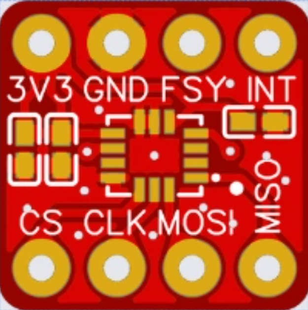
Pin Configuration and Descriptions
The ICM-42688 is available in a 14-pin LGA package. Below is the pinout description:
| Pin Number | Pin Name | Description |
|---|---|---|
| 1 | VDD | Power supply input (1.71V to 3.6V). |
| 2 | VDDIO | I/O voltage supply. |
| 3 | GND | Ground. |
| 4 | CS | Chip select for SPI interface. |
| 5 | SCL/SCLK | I²C clock / SPI clock input. |
| 6 | SDA/SDI | I²C data / SPI data input. |
| 7 | SDO | SPI data output (optional). |
| 8 | INT1 | Interrupt 1 output. |
| 9 | INT2 | Interrupt 2 output. |
| 10 | FSYNC | Frame synchronization input. |
| 11 | RESV | Reserved (do not connect). |
| 12 | RESV | Reserved (do not connect). |
| 13 | RESV | Reserved (do not connect). |
| 14 | RESV | Reserved (do not connect). |
Usage Instructions
How to Use the ICM-42688 in a Circuit
- Power Supply: Connect the VDD pin to a regulated power source (1.71V to 3.6V) and the GND pin to ground. Ensure the VDDIO pin is connected to the appropriate I/O voltage level.
- Communication Interface:
- For I²C, connect the SCL and SDA pins to the corresponding I²C lines on your microcontroller. Use pull-up resistors (typically 4.7 kΩ) on both lines.
- For SPI, connect the CS, SCLK, SDI, and SDO pins to the corresponding SPI lines on your microcontroller.
- Interrupts: Use the INT1 and/or INT2 pins to receive interrupt signals for motion events or data-ready notifications.
- Configuration: Initialize the device by configuring the gyroscope and accelerometer ranges, output data rates, and any required interrupts via the communication interface.
Important Considerations
- Bypass Reserved Pins: Do not connect any of the reserved pins (pins 11-14) to your circuit.
- Voltage Levels: Ensure the I/O voltage levels match the microcontroller's logic levels to avoid damage.
- PCB Layout: Minimize noise by placing decoupling capacitors (e.g., 0.1 µF) close to the power supply pins.
- Orientation: Mount the device with the correct orientation to ensure accurate motion tracking.
Example Code for Arduino UNO
Below is an example of interfacing the ICM-42688 with an Arduino UNO using the I²C interface:
#include <Wire.h>

// ICM-42688 I2C address
#define ICM42688_ADDR 0x68

// Register addresses
#define WHO_AM_I 0x75
#define PWR_MGMT_1 0x06
#define ACCEL_XOUT_H 0x2D

void setup() {
  Wire.begin(); // Initialize I2C communication
  Serial.begin(9600); // Initialize serial communication

  // Wake up the ICM-42688
  Wire.beginTransmission(ICM42688_ADDR);
  Wire.write(PWR_MGMT_1); // Power management register
  Wire.write(0x01); // Set to normal mode
  Wire.endTransmission();

  // Verify device ID
  Wire.beginTransmission(ICM42688_ADDR);
  Wire.write(WHO_AM_I); // WHO_AM_I register
  Wire.endTransmission();
  Wire.requestFrom(ICM42688_ADDR, 1);
  if (Wire.available()) {
    byte deviceID = Wire.read();
    if (deviceID == 0x47) { // Expected device ID for ICM-42688
      Serial.println("ICM-42688 detected!");
    } else {
      Serial.println("Device not recognized.");
    }
  }
}

void loop() {
  // Read accelerometer data
  Wire.beginTransmission(ICM42688_ADDR);
  Wire.write(ACCEL_XOUT_H); // Start with ACCEL_XOUT_H register
  Wire.endTransmission();
  Wire.requestFrom(ICM42688_ADDR, 6); // Request 6 bytes (X, Y, Z)

  if (Wire.available() == 6) {
    int16_t accelX = (Wire.read() << 8) | Wire.read();
    int16_t accelY = (Wire.read() << 8) | Wire.read();
    int16_t accelZ = (Wire.read() << 8) | Wire.read();

    // Print accelerometer data
    Serial.print("Accel X: "); Serial.print(accelX);
    Serial.print(" | Accel Y: "); Serial.print(accelY);
    Serial.print(" | Accel Z: "); Serial.println(accelZ);
  }

  delay(500); // Delay for readability
}
Troubleshooting and FAQs
Common Issues
Device Not Detected:
- Ensure the I²C address (default: 0x68) matches your configuration.
- Verify the power supply and ground connections.
- Check for proper pull-up resistors on the I²C lines.
Incorrect Data Output:
- Confirm the device is initialized with the correct configuration.
- Verify the orientation of the device on the PCB.
Communication Errors:
- Check the I²C or SPI connections for loose wires or incorrect pin assignments.
- Ensure the microcontroller's clock speed is compatible with the ICM-42688.
Tips for Troubleshooting
- Use a logic analyzer to monitor I²C or SPI communication for debugging.
- Refer to the ICM-42688 datasheet for detailed register descriptions and configuration options.
- Test the device in a static environment to verify baseline readings before using it in dynamic applications.