How to Use С2000-СП1: Examples, Pinouts, and Specs
Introduction
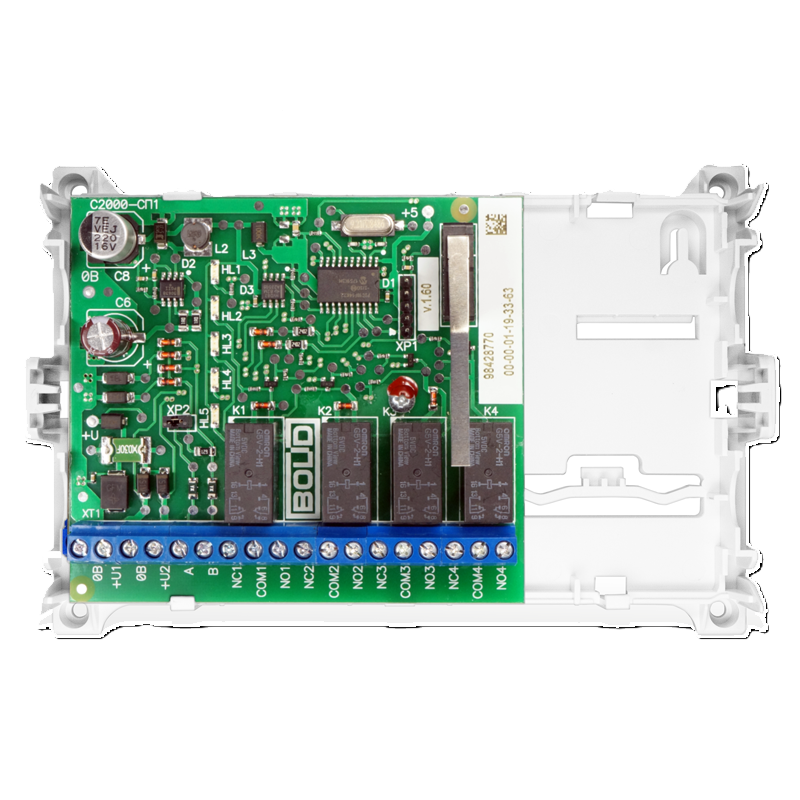
The С2000-СП1, manufactured by Bolid, is a programmable logic controller (PLC) designed for industrial automation and control applications. It features multiple input/output (I/O) channels, robust communication interfaces, and programmability, making it suitable for a wide range of tasks, including process control, machine automation, and building management systems. Its compact design and versatility allow it to integrate seamlessly into various industrial environments.
Explore Projects Built with С2000-СП1


Explore Projects Built with С2000-СП1
Common Applications
- Industrial process automation
- Machine control and monitoring
- Building management systems (e.g., HVAC, lighting control)
- Data acquisition and remote monitoring
- Security and fire alarm systems
Technical Specifications
Key Technical Details
| Parameter | Specification |
|---|---|
| Supply Voltage | 12–24 V DC |
| Power Consumption | ≤ 5 W |
| Digital Inputs | 8 channels (configurable) |
| Digital Outputs | 6 channels (relay-based) |
| Analog Inputs | 4 channels (0–10 V or 4–20 mA) |
| Communication Interfaces | RS-485, Ethernet |
| Programming Language | Ladder Logic, Function Block Diagram |
| Operating Temperature | -10°C to +50°C |
| Dimensions | 120 mm x 90 mm x 60 mm |
| Mounting | DIN rail |
Pin Configuration and Descriptions
Power and Communication Terminals
| Pin Number | Label | Description |
|---|---|---|
| 1 | +V | Positive power supply input (12–24 V DC) |
| 2 | GND | Ground (0 V) |
| 3 | RS485-A | RS-485 communication line (A) |
| 4 | RS485-B | RS-485 communication line (B) |
| 5 | ETH-TX+ | Ethernet transmit positive |
| 6 | ETH-TX- | Ethernet transmit negative |
| 7 | ETH-RX+ | Ethernet receive positive |
| 8 | ETH-RX- | Ethernet receive negative |
Input/Output Terminals
| Pin Number | Label | Description |
|---|---|---|
| 9–16 | DI1–DI8 | Digital input channels 1 to 8 |
| 17–22 | DO1–DO6 | Digital output channels 1 to 6 (relays) |
| 23–26 | AI1–AI4 | Analog input channels 1 to 4 |
Usage Instructions
How to Use the С2000-СП1 in a Circuit
- Power Connection: Connect a 12–24 V DC power supply to the
+VandGNDterminals. - Input Configuration:
- For digital inputs, connect switches, sensors, or other devices to the
DIterminals. - For analog inputs, ensure the input signal is within the supported range (0–10 V or 4–20 mA).
- For digital inputs, connect switches, sensors, or other devices to the
- Output Configuration:
- Connect actuators, relays, or other devices to the
DOterminals. - Ensure the connected devices do not exceed the relay's current rating.
- Connect actuators, relays, or other devices to the
- Communication Setup:
- Use the RS-485 interface for serial communication with other devices.
- For Ethernet communication, connect the appropriate cables to the
ETHterminals.
- Programming:
- Use compatible software to program the PLC using Ladder Logic or Function Block Diagram.
- Upload the program to the PLC via the RS-485 or Ethernet interface.
Important Considerations and Best Practices
- Power Supply: Use a regulated DC power supply to avoid voltage fluctuations.
- Wiring: Ensure proper insulation and secure connections to prevent short circuits.
- Grounding: Connect the
GNDterminal to a reliable ground to minimize electrical noise. - Programming: Test the program in a simulation environment before deploying it to the PLC.
- Environment: Install the PLC in a well-ventilated area within the specified temperature range.
Example: Connecting to an Arduino UNO
The С2000-СП1 can communicate with an Arduino UNO via the RS-485 interface. Below is an example Arduino sketch for reading data from the PLC.
#include <ModbusMaster.h>

// Instantiate ModbusMaster object
ModbusMaster node;

void setup() {
  Serial.begin(9600); // Initialize serial communication
  node.begin(1, Serial); // Set Modbus ID to 1 and use Serial for communication
}

void loop() {
  uint8_t result;
  uint16_t data;

  // Read a register from the PLC (e.g., register 0x0001)
  result = node.readHoldingRegisters(0x0001, 1);

  if (result == node.ku8MBSuccess) {
    data = node.getResponseBuffer(0); // Get the data from the response buffer
    Serial.print("Register Value: ");
    Serial.println(data); // Print the value to the Serial Monitor
  } else {
    Serial.println("Communication Error"); // Handle communication errors
  }

  delay(1000); // Wait 1 second before the next request
}
Troubleshooting and FAQs
Common Issues and Solutions
PLC Not Powering On:
- Cause: Incorrect power supply voltage or loose connections.
- Solution: Verify the power supply voltage (12–24 V DC) and check all connections.
No Communication via RS-485:
- Cause: Incorrect wiring or mismatched baud rate.
- Solution: Ensure proper wiring of the
RS485-AandRS485-Blines. Verify that the baud rate matches the PLC's configuration.
Digital Inputs Not Responding:
- Cause: Faulty input device or incorrect wiring.
- Solution: Test the input device separately and check the wiring to the
DIterminals.
Analog Input Values Are Incorrect:
- Cause: Signal out of range or improper configuration.
- Solution: Ensure the input signal is within the 0–10 V or 4–20 mA range. Configure the input type correctly in the PLC software.
Relay Outputs Not Activating:
- Cause: Exceeded current rating or faulty relay.
- Solution: Check the connected load and ensure it does not exceed the relay's rating. Replace the relay if necessary.
FAQs
Q1: Can the С2000-СП1 be used in outdoor environments?
A1: The PLC is not designed for direct outdoor use. It should be installed in a protective enclosure to shield it from moisture, dust, and extreme temperatures.
Q2: What software is compatible with the С2000-СП1?
A2: The PLC can be programmed using Bolid's proprietary software, which supports Ladder Logic and Function Block Diagram programming.
Q3: How do I reset the PLC to factory settings?
A3: Refer to the manufacturer's manual for the specific reset procedure, which typically involves a combination of hardware and software steps.
Q4: Can I expand the I/O channels?
A4: Yes, the С2000-СП1 supports expansion modules for additional I/O channels. Consult the manufacturer for compatible modules.