How to Use arduino uno: Examples, Pinouts, and Specs
Introduction
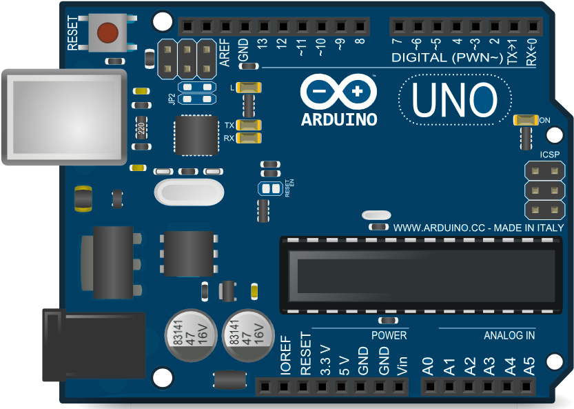
The Arduino Uno, manufactured by ARDUINO, is a microcontroller board based on the ATmega328P. It is widely used for building digital devices and interactive objects that can sense and control the physical world. The board is designed to be beginner-friendly while offering advanced features for experienced users. Its open-source nature and extensive community support make it a popular choice for prototyping, learning, and developing embedded systems.
Explore Projects Built with arduino uno
Explore Projects Built with arduino uno
Common Applications and Use Cases
- Prototyping IoT (Internet of Things) devices
- Robotics and automation projects
- Sensor-based data acquisition systems
- Home automation and smart devices
- Educational tools for learning programming and electronics
- Interactive art installations
Technical Specifications
The Arduino Uno is equipped with a range of features that make it versatile and easy to use. Below are its key technical details:
Key Technical Details
| Specification | Value |
|---|---|
| Microcontroller | ATmega328P |
| Operating Voltage | 5V |
| Input Voltage (recommended) | 7-12V |
| Input Voltage (limit) | 6-20V |
| Digital I/O Pins | 14 (6 provide PWM output) |
| Analog Input Pins | 6 |
| DC Current per I/O Pin | 20 mA |
| Flash Memory | 32 KB (0.5 KB used by bootloader) |
| SRAM | 2 KB |
| EEPROM | 1 KB |
| Clock Speed | 16 MHz |
| USB Connector | Type-B |
| Dimensions | 68.6 mm x 53.4 mm |
| Weight | 25 g |
Pin Configuration and Descriptions
The Arduino Uno has a total of 28 pins, including digital, analog, power, and communication pins. Below is a detailed description of the pin configuration:
Digital Pins
| Pin Number | Functionality |
|---|---|
| 0 (RX) | Serial Receive (UART) |
| 1 (TX) | Serial Transmit (UART) |
| 2-13 | General-purpose digital I/O |
| 3, 5, 6, 9, 10, 11 | PWM output |
Analog Pins
| Pin Number | Functionality |
|---|---|
| A0-A5 | Analog input (10-bit resolution) |
Power Pins
| Pin Name | Functionality |
|---|---|
| VIN | Input voltage to the board |
| 5V | Regulated 5V output |
| 3.3V | Regulated 3.3V output |
| GND | Ground |
| RESET | Resets the microcontroller |
Communication Pins
| Pin Name | Functionality |
|---|---|
| SDA | I2C Data Line |
| SCL | I2C Clock Line |
| RX | UART Receive |
| TX | UART Transmit |
Usage Instructions
The Arduino Uno is designed to be easy to use, even for beginners. Follow the steps below to get started:
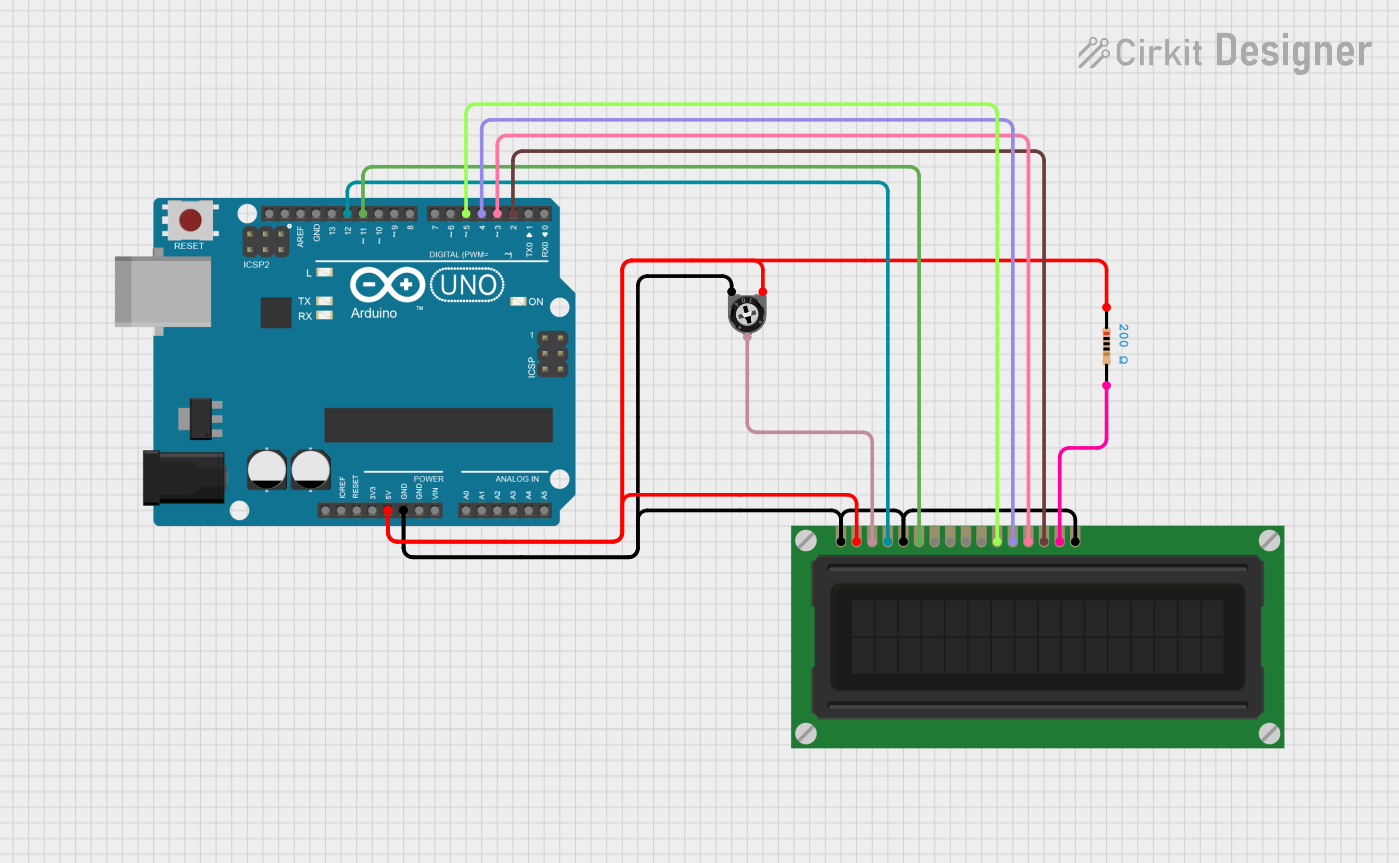
How to Use the Arduino Uno in a Circuit
Power the Board:
- Connect the Arduino Uno to your computer using a USB Type-B cable.
- Alternatively, use an external power supply (7-12V) via the VIN pin or DC barrel jack.
Install the Arduino IDE:
- Download and install the Arduino IDE from the official Arduino website.
- Ensure the correct drivers are installed for your operating system.
Write and Upload Code:
- Open the Arduino IDE and write your program (called a "sketch").
- Select the correct board (
Arduino Uno) and port from the Tools menu. - Click the "Upload" button to transfer the code to the board.
Connect Components:
- Use jumper wires to connect sensors, actuators, or other components to the appropriate pins.
- Refer to the pin configuration table for guidance.
Run the Program:
- Once the code is uploaded, the Arduino Uno will execute it automatically.
- Monitor the output using the Serial Monitor in the Arduino IDE, if needed.
Important Considerations and Best Practices
- Voltage Levels: Ensure that the input voltage does not exceed the recommended range (7-12V).
- Pin Current Limits: Do not draw more than 20 mA from any I/O pin to avoid damaging the microcontroller.
- Static Protection: Handle the board carefully to prevent damage from electrostatic discharge (ESD).
- Code Optimization: Use efficient coding practices to make the most of the limited memory and processing power.
Example Code for Arduino Uno
Below is an example of a simple program to blink an LED connected to pin 13:
// This program blinks an LED connected to pin 13 on the Arduino Uno.
// The LED will turn on for 1 second, then off for 1 second, repeatedly.

void setup() {
  pinMode(13, OUTPUT); // Set pin 13 as an output pin
}

void loop() {
  digitalWrite(13, HIGH); // Turn the LED on
  delay(1000);            // Wait for 1 second
  digitalWrite(13, LOW);  // Turn the LED off
  delay(1000);            // Wait for 1 second
}
Troubleshooting and FAQs
Common Issues and Solutions
The Arduino Uno is not detected by the computer:
- Ensure the USB cable is properly connected and functional.
- Check that the correct drivers are installed.
- Try using a different USB port or cable.
Code does not upload to the board:
- Verify that the correct board (
Arduino Uno) and port are selected in the Arduino IDE. - Press the RESET button on the board and try uploading again.
- Ensure no other program is using the same COM port.
- Verify that the correct board (
Components connected to the board are not working:
- Double-check the wiring and connections.
- Ensure the components are compatible with the Arduino Uno.
- Test the components individually to confirm they are functional.
The board overheats or behaves erratically:
- Check for short circuits or excessive current draw.
- Ensure the input voltage is within the recommended range (7-12V).
FAQs
Q: Can I power the Arduino Uno with a battery?
A: Yes, you can use a 9V battery connected to the DC barrel jack or VIN pin.
Q: How do I reset the Arduino Uno?
A: Press the RESET button on the board, or connect the RESET pin to GND momentarily.
Q: Can I use the Arduino Uno for wireless communication?
A: Yes, you can use external modules like Bluetooth, Wi-Fi, or RF transceivers to enable wireless communication.
Q: Is the Arduino Uno compatible with shields?
A: Yes, the Arduino Uno is compatible with a wide range of shields designed for the Uno form factor.
This concludes the documentation for the Arduino Uno. For further assistance, refer to the official Arduino website or community forums.