Cirkit Designer Logo
Cirkit Designer
Your all-in-one circuit design IDE
Home / 
Component Documentation

How to Use DC-DC Step-Down Buck Converter Power Supply Module 24V 12V 9V to 5V 5A 25W: Examples, Pinouts, and Specs

Image of DC-DC Step-Down Buck Converter Power Supply Module 24V 12V 9V to 5V 5A 25W
Cirkit Designer LogoDesign with DC-DC Step-Down Buck Converter Power Supply Module 24V 12V 9V to 5V 5A 25W in Cirkit Designer

Introduction

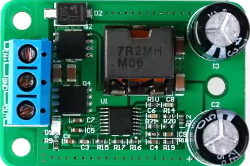
The DC-DC Step-Down Buck Converter Power Supply Module is a versatile and efficient voltage regulator designed to step down higher input voltages (24V, 12V, 9V) to a stable 5V output. With a maximum current output of 5A and a power rating of 25W, this module is ideal for powering low-voltage devices such as microcontrollers, sensors, and USB-powered devices. Its compact design and high efficiency make it a popular choice for embedded systems, robotics, and portable electronics.

Explore Projects Built with DC-DC Step-Down Buck Converter Power Supply Module 24V 12V 9V to 5V 5A 25W

Use Cirkit Designer to design, explore, and prototype these projects online. Some projects support real-time simulation. Click "Open Project" to start designing instantly!
Battery-Powered DC-DC Converter System for Multi-Voltage Power Distribution
Image of test 1 ih: A project utilizing DC-DC Step-Down Buck Converter Power Supply Module 24V 12V 9V to 5V 5A 25W in a practical application
This circuit converts a 38.5V battery output to multiple lower voltage levels using a series of DC-DC converters and a power module. It includes an emergency stop switch for safety and distributes power to various components such as a relay module, USB ports, and a bus servo adaptor.
Cirkit Designer LogoOpen Project in Cirkit Designer
Battery-Powered UPS with Step-Down Buck Converter and BMS
Image of Mini ups: A project utilizing DC-DC Step-Down Buck Converter Power Supply Module 24V 12V 9V to 5V 5A 25W in a practical application
This circuit is a power management system that steps down a 240V AC input to a lower DC voltage using a buck converter, which then powers a 40W UPS. The UPS is controlled by a rocker switch and is backed up by a battery management system (BMS) connected to three 3.7V batteries in series, ensuring continuous power supply.
Cirkit Designer LogoOpen Project in Cirkit Designer
USB Power Supply with Overcurrent Protection
Image of USB Charging port: A project utilizing DC-DC Step-Down Buck Converter Power Supply Module 24V 12V 9V to 5V 5A 25W in a practical application
This circuit is designed to step down voltage from a 12V battery to a lower voltage suitable for USB devices. It includes a buck converter connected to the battery through a fuse and fuse holder for overcurrent protection. The output of the buck converter is connected to a USB female port, providing a regulated power supply for USB-powered devices.
Cirkit Designer LogoOpen Project in Cirkit Designer
DC-DC Converter and Relay Module Power Distribution System
Image of relay: A project utilizing DC-DC Step-Down Buck Converter Power Supply Module 24V 12V 9V to 5V 5A 25W in a practical application
This circuit consists of a DC-DC converter powering a 6-channel power module, which in turn supplies 5V to a 2-relay module. The power module distributes the converted voltage to the relay module, enabling it to control external devices.
Cirkit Designer LogoOpen Project in Cirkit Designer

Explore Projects Built with DC-DC Step-Down Buck Converter Power Supply Module 24V 12V 9V to 5V 5A 25W

Use Cirkit Designer to design, explore, and prototype these projects online. Some projects support real-time simulation. Click "Open Project" to start designing instantly!
Image of test 1 ih: A project utilizing DC-DC Step-Down Buck Converter Power Supply Module 24V 12V 9V to 5V 5A 25W in a practical application
Battery-Powered DC-DC Converter System for Multi-Voltage Power Distribution
This circuit converts a 38.5V battery output to multiple lower voltage levels using a series of DC-DC converters and a power module. It includes an emergency stop switch for safety and distributes power to various components such as a relay module, USB ports, and a bus servo adaptor.
Cirkit Designer LogoOpen Project in Cirkit Designer
Image of Mini ups: A project utilizing DC-DC Step-Down Buck Converter Power Supply Module 24V 12V 9V to 5V 5A 25W in a practical application
Battery-Powered UPS with Step-Down Buck Converter and BMS
This circuit is a power management system that steps down a 240V AC input to a lower DC voltage using a buck converter, which then powers a 40W UPS. The UPS is controlled by a rocker switch and is backed up by a battery management system (BMS) connected to three 3.7V batteries in series, ensuring continuous power supply.
Cirkit Designer LogoOpen Project in Cirkit Designer
Image of USB Charging port: A project utilizing DC-DC Step-Down Buck Converter Power Supply Module 24V 12V 9V to 5V 5A 25W in a practical application
USB Power Supply with Overcurrent Protection
This circuit is designed to step down voltage from a 12V battery to a lower voltage suitable for USB devices. It includes a buck converter connected to the battery through a fuse and fuse holder for overcurrent protection. The output of the buck converter is connected to a USB female port, providing a regulated power supply for USB-powered devices.
Cirkit Designer LogoOpen Project in Cirkit Designer
Image of relay: A project utilizing DC-DC Step-Down Buck Converter Power Supply Module 24V 12V 9V to 5V 5A 25W in a practical application
DC-DC Converter and Relay Module Power Distribution System
This circuit consists of a DC-DC converter powering a 6-channel power module, which in turn supplies 5V to a 2-relay module. The power module distributes the converted voltage to the relay module, enabling it to control external devices.
Cirkit Designer LogoOpen Project in Cirkit Designer

Common Applications

  • Powering microcontrollers (e.g., Arduino, Raspberry Pi)
  • USB device charging
  • Robotics and automation systems
  • Battery-powered devices
  • LED lighting systems

Technical Specifications

Key Specifications

Parameter Value
Input Voltage Range 6V to 32V
Output Voltage 5V (fixed)
Maximum Output Current 5A
Maximum Output Power 25W
Efficiency Up to 96%
Operating Temperature -40°C to +85°C
Dimensions ~60mm x 21mm x 14mm

Pin Configuration and Descriptions

Pin Name Description
VIN+ Positive input voltage (6V to 32V)
VIN- Negative input voltage (ground)
VOUT+ Positive output voltage (5V)
VOUT- Negative output voltage (ground)

Usage Instructions

How to Use the Component in a Circuit

  1. Connect the Input Voltage:

    • Connect the positive terminal of your power source (6V to 32V) to the VIN+ pin.
    • Connect the negative terminal of your power source to the VIN- pin.
  2. Connect the Output Load:

    • Connect the positive terminal of your load (e.g., microcontroller, USB device) to the VOUT+ pin.
    • Connect the negative terminal of your load to the VOUT- pin.
  3. Verify Connections:

    • Double-check all connections to ensure proper polarity and secure wiring.
  4. Power On:

    • Turn on the power source. The module will regulate the input voltage to a stable 5V output.

Important Considerations and Best Practices

  • Input Voltage Range: Ensure the input voltage is within the specified range (6V to 32V). Exceeding this range may damage the module.
  • Heat Dissipation: At high currents (e.g., 5A), the module may generate heat. Use a heatsink or active cooling if necessary.
  • Load Requirements: Ensure the connected load does not exceed the maximum output current (5A) or power (25W).
  • Polarity Protection: Double-check the polarity of the input and output connections to avoid damage.

Example: Using with an Arduino UNO

The DC-DC buck converter can be used to power an Arduino UNO from a 12V battery. Below is an example circuit and Arduino code to blink an LED.

Circuit Connections

  • Connect the 12V battery's positive terminal to VIN+ and negative terminal to VIN-.
  • Connect VOUT+ to the Arduino's 5V pin and VOUT- to the Arduino's GND pin.
  • Connect an LED with a 220-ohm resistor to Arduino pin 13.

Arduino Code

// Simple LED blink example for Arduino UNO
// This code blinks an LED connected to pin 13 every second.

void setup() {
  pinMode(13, OUTPUT); // Set pin 13 as an output
}

void loop() {
  digitalWrite(13, HIGH); // Turn the LED on
  delay(1000);            // Wait for 1 second
  digitalWrite(13, LOW);  // Turn the LED off
  delay(1000);            // Wait for 1 second
}

Troubleshooting and FAQs

Common Issues and Solutions

  1. No Output Voltage:

    • Cause: Incorrect input voltage or loose connections.
    • Solution: Verify that the input voltage is within the 6V to 32V range and check all connections.
  2. Overheating:

    • Cause: High current draw or insufficient cooling.
    • Solution: Reduce the load current or add a heatsink/active cooling to the module.
  3. Output Voltage Fluctuations:

    • Cause: Input voltage instability or excessive load.
    • Solution: Use a stable power source and ensure the load does not exceed 5A.
  4. Module Not Working After Connection:

    • Cause: Reverse polarity or overvoltage.
    • Solution: Check the polarity of the input and output connections. Replace the module if damaged.

FAQs

  • Q: Can this module output voltages other than 5V?
    A: No, this module has a fixed 5V output.

  • Q: Can I use this module to charge a smartphone?
    A: Yes, as long as the input voltage is within range and the smartphone's charging current does not exceed 5A.

  • Q: Is the module waterproof?
    A: No, the module is not waterproof. Use it in a dry environment or enclose it in a waterproof case.

  • Q: Can I use this module with a solar panel?
    A: Yes, as long as the solar panel's output voltage is within the 6V to 32V range.