How to Use Zero Delay USB Arcade Encoder: Examples, Pinouts, and Specs
Introduction
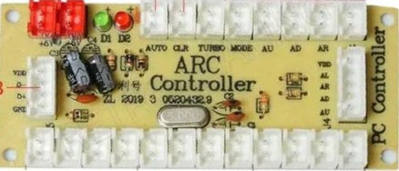
The Zero Delay USB Arcade Encoder is a versatile device designed to convert arcade-style controls, such as joysticks and push buttons, into USB signals. This allows users to connect arcade controls to computers, gaming consoles, or other USB-compatible devices for gaming or custom control applications. As its name suggests, the encoder is optimized for minimal input lag, ensuring a seamless and responsive gaming experience.
Explore Projects Built with Zero Delay USB Arcade Encoder
Explore Projects Built with Zero Delay USB Arcade Encoder
Common Applications and Use Cases
- DIY arcade cabinet projects
- Retro gaming setups
- Custom game controllers
- PC-based gaming systems
- Emulation platforms (e.g., RetroPie, MAME)
- Robotics or other projects requiring custom input devices
Technical Specifications
The Zero Delay USB Arcade Encoder is designed for simplicity and compatibility. Below are its key technical details:
General Specifications
| Parameter | Value |
|---|---|
| Input Voltage | 5V DC (via USB connection) |
| Interface Type | USB 2.0 |
| Supported Joystick Type | 5-pin joystick (digital input) |
| Button Inputs | Up to 12 individual buttons |
| Compatibility | Windows, Linux, macOS, Raspberry Pi, and gaming consoles (e.g., PS3) |
| Input Lag | Zero delay (optimized for real-time response) |
Pin Configuration and Descriptions
The encoder features multiple connectors for joysticks and buttons. Below is the pin configuration:
Joystick Connector (5-pin)
| Pin Number | Signal Name | Description |
|---|---|---|
| 1 | GND | Ground connection |
| 2 | UP | Joystick UP direction input |
| 3 | DOWN | Joystick DOWN direction input |
| 4 | LEFT | Joystick LEFT direction input |
| 5 | RIGHT | Joystick RIGHT direction input |
Button Inputs
| Pin Label | Description |
|---|---|
| B1 - B12 | Button inputs for up to 12 individual buttons |
| GND | Ground connection for button inputs |
USB Connector
| Pin Number | Signal Name | Description |
|---|---|---|
| 1 | VCC | 5V power supply from USB |
| 2 | D- | USB data line (-) |
| 3 | D+ | USB data line (+) |
| 4 | GND | Ground connection |
Usage Instructions
How to Use the Component in a Circuit
- Connect the Joystick: Attach the 5-pin joystick connector to the encoder's joystick port. Ensure the pins are aligned correctly.
- Connect the Buttons: Use the provided wires to connect each button to the corresponding input pin (B1 to B12). Connect the other terminal of each button to a GND pin.
- Connect to USB: Plug the encoder into a USB port on your computer, gaming console, or Raspberry Pi using the included USB cable.
- Test the Inputs: Once connected, the encoder will be recognized as a standard USB game controller. Use your operating system's game controller settings to test the joystick and button inputs.
Important Considerations and Best Practices
- Power Supply: The encoder is powered directly via USB, so no external power supply is required.
- Button Debouncing: The encoder handles button debouncing internally, ensuring reliable input detection.
- Joystick Compatibility: Ensure the joystick is a 5-pin digital type. Analog joysticks are not supported.
- Mounting: Secure the encoder in your project enclosure to prevent accidental disconnections.
- Driver Installation: On most systems, no additional drivers are required. The encoder is plug-and-play.
Example Code for Arduino UNO
While the Zero Delay USB Arcade Encoder is primarily a USB device, you can interface it with an Arduino UNO for custom projects. Below is an example of how to read button inputs from the encoder:
// Example code to read button inputs from the Zero Delay USB Arcade Encoder
// Connect the encoder's button outputs (e.g., B1, B2) to Arduino digital pins.

const int button1Pin = 2; // Connect B1 to digital pin 2
const int button2Pin = 3; // Connect B2 to digital pin 3

void setup() {
  pinMode(button1Pin, INPUT_PULLUP); // Set button 1 pin as input with pull-up
  pinMode(button2Pin, INPUT_PULLUP); // Set button 2 pin as input with pull-up
  Serial.begin(9600); // Initialize serial communication
}

void loop() {
  // Read the state of button 1
  int button1State = digitalRead(button1Pin);
  // Read the state of button 2
  int button2State = digitalRead(button2Pin);

  // Print button states to the serial monitor
  Serial.print("Button 1: ");
  Serial.println(button1State == LOW ? "Pressed" : "Released");
  Serial.print("Button 2: ");
  Serial.println(button2State == LOW ? "Pressed" : "Released");

  delay(100); // Small delay to avoid spamming the serial monitor
}
Troubleshooting and FAQs
Common Issues and Solutions
Joystick or Buttons Not Responding
- Solution: Check all connections to ensure they are secure and properly aligned. Verify that the joystick and buttons are functional by testing them individually.
Encoder Not Recognized by the Computer
- Solution: Ensure the USB cable is securely connected. Try a different USB port or cable. On older operating systems, ensure USB drivers are up to date.
Input Lag
- Solution: The encoder is designed for zero delay. If you experience lag, check for issues with your computer or gaming console, such as high CPU usage or background processes.
Button Inputs Stuck or Repeating
- Solution: Verify that no buttons are physically stuck. Check the wiring for shorts or loose connections.
FAQs
Q: Can I use this encoder with a Raspberry Pi?
- A: Yes, the encoder is fully compatible with Raspberry Pi and works with emulation platforms like RetroPie.
Q: Does it support analog joysticks?
- A: No, the encoder only supports 5-pin digital joysticks.
Q: How many buttons can I connect?
- A: You can connect up to 12 buttons.
Q: Do I need to install drivers?
- A: No, the encoder is plug-and-play on most systems, including Windows, Linux, and macOS.
This concludes the documentation for the Zero Delay USB Arcade Encoder.