How to Use WAGO Connector: Examples, Pinouts, and Specs
Introduction
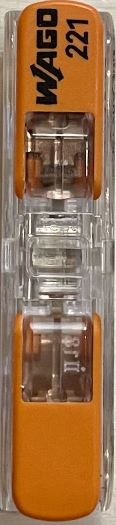
The WAGO Connector 221-2411 is a compact and reliable electrical connector designed for quick and solderless wire connections. This innovative connector utilizes WAGO's unique spring pressure connection technology to ensure a secure and durable bond between wires. Commonly used in a variety of applications, including residential wiring, industrial control systems, and consumer electronics, the WAGO Connector simplifies the process of wire splicing and junctions.
Explore Projects Built with WAGO Connector
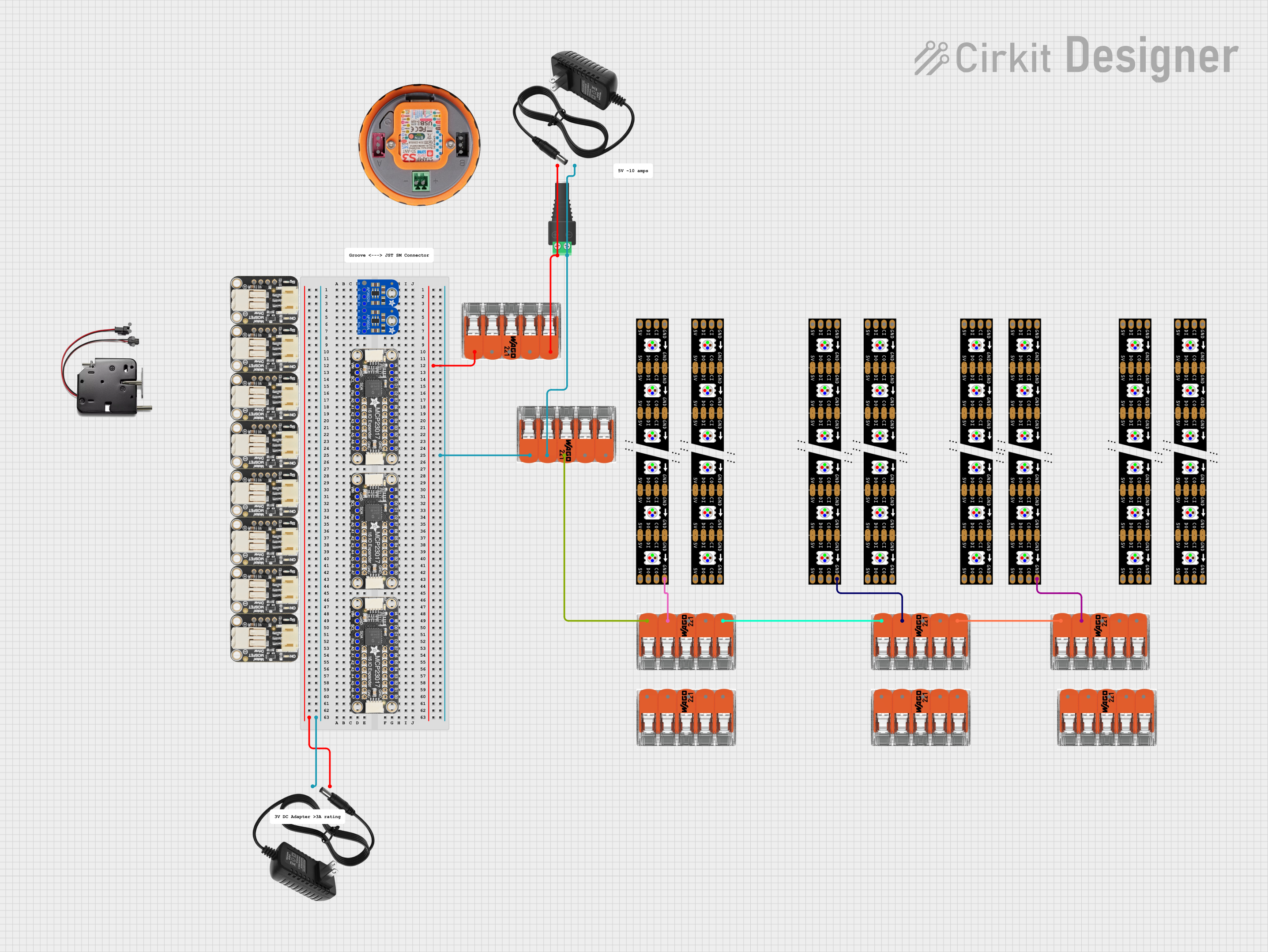


Explore Projects Built with WAGO Connector
Technical Specifications
Key Technical Details
- Rated Voltage: Up to 450V
- Rated Impulse Voltage: 4 kV
- Rated Current: Up to 32A
- Connection Method: CAGE CLAMP® connection
- Wire Type: Stranded or solid
- Wire Size: 0.14 to 4 mm² (24-12 AWG)
- Strip Length: 11 mm
- Number of Connection Points: 2
- Number of Potentials: 1
- Actuation Type: Lever
- Material: Polyamide 66
- Temperature Range: -40°C to 85°C
- Approvals: CE, ENEC, UL
Pin Configuration and Descriptions
| Pin No. | Description |
|---|---|
| 1 | Wire entry for conductor 1 |
| 2 | Wire entry for conductor 2 |
Usage Instructions
How to Use the WAGO Connector in a Circuit
Preparation:
- Ensure the power to the circuit is turned off before making connections.
- Strip the wire ends to 11 mm, ensuring a clean and accurate strip for a reliable connection.
Insertion:
- Lift the orange lever on the connector to open the clamping unit.
- Insert the stripped wire end fully into the connector's entry point.
- Lower the lever to secure the wire in place. A proper connection will have the wire held firmly without any movement.
Testing:
- Once all connections are made, perform a pull test to ensure that the wires are securely fastened.
- Use a multimeter to check for continuity and proper insulation.
Important Considerations and Best Practices
- Do not exceed the rated voltage and current specifications to prevent overheating and potential failure.
- Ensure that the wires are free of insulation damage, corrosion, and are not frayed before insertion.
- Use wires that are within the specified gauge range for optimal performance.
- Do not use the connector in environments that exceed the specified temperature range.
- For applications that are prone to vibration, secure the wires and connectors to prevent loosening over time.
Troubleshooting and FAQs
Common Issues and Solutions
- Loose Wires: If a wire comes loose, ensure that the lever is fully closed and the wire is stripped to the correct length and inserted fully.
- No Continuity: Check for proper wire insertion and that the wire is not damaged. Ensure that the connector is not damaged and is functioning correctly.
- Overheating: If the connector is overheating, immediately disconnect the power and check if the current rating has been exceeded or if there is a short circuit.
FAQs
Q: Can the WAGO Connector 221-2411 be reused? A: Yes, the connector is designed to be reusable. Simply lift the lever, remove the wire, and it's ready for another connection.
Q: Is it necessary to twist the wires before inserting them into the connector? A: No, twisting the wires is not required. The connector is designed to clamp onto individual strands effectively.
Q: Can the WAGO Connector be used outdoors? A: The WAGO Connector 221-2411 is not rated for outdoor use unless placed within a suitable enclosure that provides protection from the elements.
Q: Are there any special tools required for using the WAGO Connector? A: No special tools are required. However, a wire stripper is necessary to prepare the wire ends before insertion.
Example Code for Arduino UNO Connection
// Example code to demonstrate the use of a WAGO Connector with an Arduino UNO
// The WAGO Connector is used to connect an external LED to pin 13

void setup() {
  pinMode(13, OUTPUT); // Set the digital pin 13 as output
}

void loop() {
  digitalWrite(13, HIGH);   // Turn the LED on
  delay(1000);              // Wait for a second
  digitalWrite(13, LOW);    // Turn the LED off
  delay(1000);              // Wait for a second
}

// Note: The WAGO Connector is used to connect the anode of the LED and a resistor
// to pin 13, and the cathode to the ground. Ensure the power is off before making
// connections with the WAGO Connector.
Remember to follow the usage instructions when connecting wires to the WAGO Connector. The example code provided is a simple blink sketch that can be used to test the connection made with the WAGO Connector.